Operator’s manual df32, 2 “step-by-step” assembly of pump head – Watson-Marlow DF32 User Manual
Page 18
Operator’s manual
DF32
Rev.: 1.03 Date: 2007-03-12 Page 18 of 32
File:
DF32 OM 1.03 EN
Position no
Quantities
Description
Item 5
2 pcs
O-ring (Viton)
Item 7
1 pcs
Straight connector
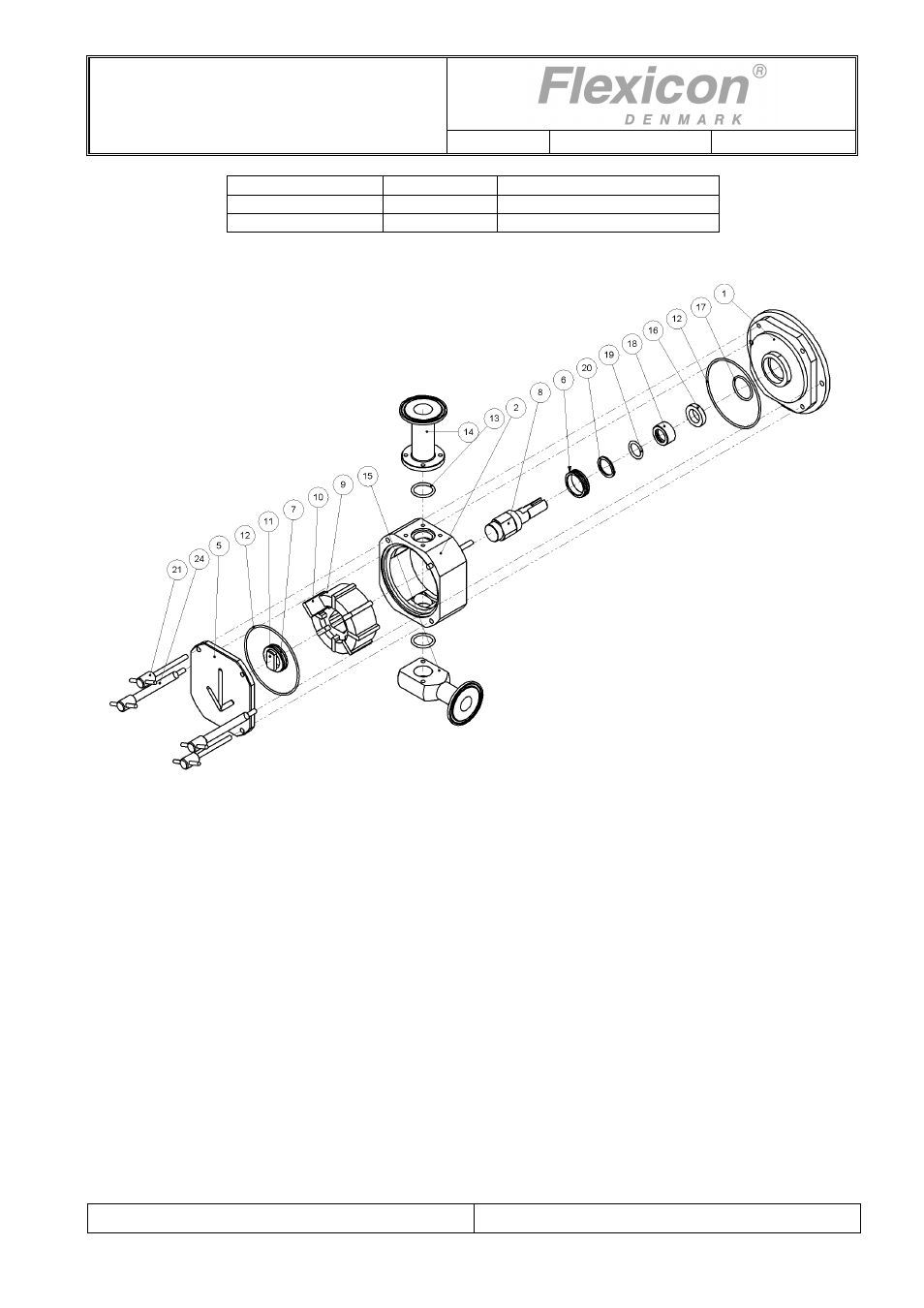
7.2 “Step-by-step” assembly of pump head
Fig. 7.2
Step Action
1
Place the rear part (1) with the curved rim facing upwards.
The centre hole should be placed above a hole or a groove with a depth of 5 cm.
2
Mount the O-ring (12) on the rear part.
3
If the ceramic ring (16) and the O-ring (17) have been removed from the rear part, they must be
mounted again. The O-ring first, and then the ceramic ring.
Use the supplied tool when mounting (and dismounting) the ceramic ring.
Note: The chamfered edge on the ceramic ring must face the rear side of the pump.
4
Mount the O-ring (7) on the bearing (6), and place both on the shaft (8).
Then put the wave spring (20) on the shaft.
Mount the Quad seal (19) into the sealing ring (18), and place both on the shaft, make sure that
the flat face in the sealing ring matched the corresponding face on the shaft.
5
Place the shaft assembly in the rear part.
6
Fit the pump housing (2) to the rear part. The longer pin on the pump housing should be fitted into
the hole in the rear part. This indicates correct positioning.
7
Mount the driving hub (9) on the shaft.
8
Mount the impeller plates (10) into the grooves of the driving hub.