Slip -3, Supv -3, T1 dte -3 – Verilink PRISM 3101 (34-00212) Product Manual User Manual
Page 13
Installation 2-3
PRISM 3101/3102
2-B displays the pinout assignments for the 8-pin modular
LAN connection.
Configure the LAN interface before connecting the PRISM
3101/3102 to the LAN network. See the section
SNMP Configuration on page 3-15 for specific information.
SLIP
The SLIP port bit rates are configured through Switch S1
(page 3-1). This port is a DCE port configured for 8 bits, no
parity, and 1 stop bit. The physical connections are 8-pin
modular jacks (electrically RS-232). Figure 2-5 provides
the pinout assignments. Refer to the section
Ordering Information on page 1-4 for cable information.
The SLIP port may be used to manage the unit. This port
allows access to the embedded SNMP agent used for trap
reporting or SNMP management. You may access this port
through either a direct connection or a dial-up connection
via an AT command set compatible modem. The modem
should be optioned to ignore DTR, enable auto answer,
inhibit command echo, and return verbose result codes.
Serial bit rates can be set from 9.6 kbps to 56 kbps.
If you call the unit and send the BREAK com-
mand before receiving the CONNECT message,
the modem will hang-up.
SUPV
The SUPV port bit rates are configured through Switch S1
(page 3-1) and programmed through the Management Ports
menu on page 3-16. This port is a DCE port configured for
8 bits, no parity, and 1 stop bit. The physical connections are
8-pin modular jacks (electrically RS-232). Figure 2-5 pro-
vides the pinout assignments. Refer to the section
Ordering Information on page 1-4 for cable information.
The unit firmware may be accessed through this port (see
Software Configuration on page 3 -3) as well as the Call On
Alarm feature (page 3-16). You may access this port
through either a direct connection or a dial-up connection
via an AT command set compatible modem. The modem
should be optioned to ignore DTR, enable auto answer,
inhibit command echo, and return verbose result codes.
Serial bit rates can be set from 1200 bps to 19200 bps.
If you call the unit and send the BREAK com-
mand before receiving the CONNECT message,
the modem will hang-up.
T1 DTE
The T1 DTE port bit rates are configured through Switch S4
(page 3-3). The physical connection is an 8-pin modular
jack. Table 2-C provides the pinout assignments. Any chan-
nel not mapped to a data port is routed to the T1 DTE inter-
face. T1 DTE port linecoding is not dependent on the
Table 2-B Token Ring Pinout Assignments
Pin
Token Ring Interface
3
Data Out (-)
4
Data In (+)
5 Data
In
(-)
6
Data Out (+)
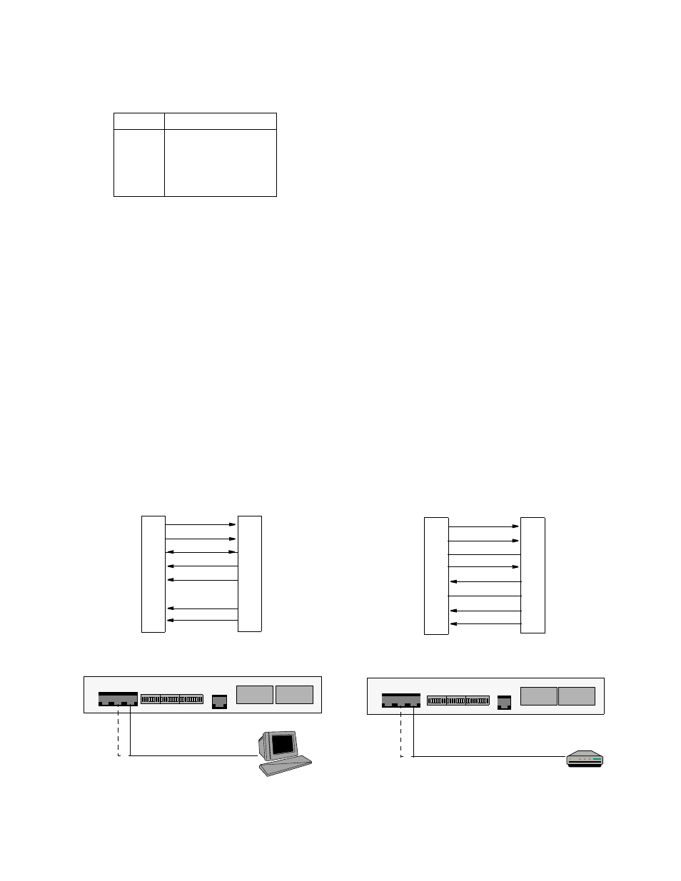
PRISM 3102 Rear Panel
PRISM 3102 Rear Panel
PC
Modem
RS-232 to Modem
RS-232 to Terminal
DCD Out
1
CTS Out
2
Frame Gnd
3
Data Out
4
Data In
5
Signal Gnd
6
RTS
In 7
DTR
In 8
PC (DTE)
S
UPV
/S
LIP
Port
1 DCD
8
CTS
5
Frame Gnd
2
RXD
3
TXD
NC Signal Gnd
7
RTS
4
DTR
8-Pin
DB-9
PN# 9-1001-073-2
PN# 9-1001-083-1
Modular
DTR Out
1
RTS Out
2
Frame Gnd
3
Data Out
4
Data In
5
Signal Gnd
6
CTS
In 7
DCD
In 8
Modem (DCE)
S
UPV
/S
LIP
Port
20 DTR
4
RTS
1
Frame Gnd
2
TXD
3
RXD
7
Signal Gnd
5
CTS
8
DCD
8-Pin
DB-25
Modular
Figure 2-5 SUPV and SLIP Terminal/Modem Connections