Power connection, Power failure, Power connection -4 power failure -4 – Verilink PRISM 3002 (34-00277) Product Manual User Manual
Page 16: Figure 2-2
2-4
I
NSTALLATION
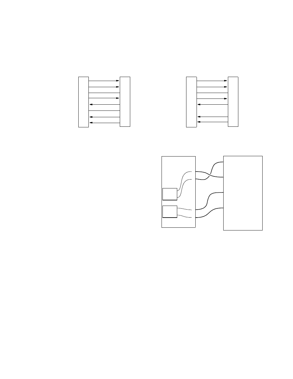
The SUPV port bit rates are configured through Switch S1 (see SUPV Port Bit
Rate on page 3-2) and programmed through the Management Ports menu on page
4-22. This port is a DCE port configured for 8 bits, no parity, and 1 stop bit. The
physical connections are 8 -pin modular jacks (electrically RS-232). Figure 2-2
provides the pinout assignments. Refer to Table 1-2 on page 1 -5 for cable
information.
Power
Connection
Power to the 3002 is supplied
through the card-edge connection
when the unit is installed in the
1024 chassis. The 3002 requires a
-48 VDC power source capable
of supplying a 150 -mA current
from the chassis. All units in the
chassis are powered by -48 VDC
sources which are connected to
the 6 -position terminal strip,
TB1, on the rear of the 1024
chassis as shown in Figure 2-3.
Power
Failure
The PRISM 3002 provides non -volatile memory retention of the unit configuration
in case of a power failure. This feature allows the unit to automatically restore
normal service following a power loss. When power is applied to the unit, the front
panel indicators flash for approximately five seconds as the unit starts up.
Figure 2-2 SUPV Terminal/Modem Connections
DTR Out
1
RTS Out
2
Frame Gnd
3
Data Out
4
Data In
5
Signal Gnd 6
CTS
In 7
DCD
In 8
PC (DTE)
SUPV Port
1 DCD
8
CTS
5
Frame Gnd
2
RXD
3
TXD
NC Signal Gnd
7
RTS
4
DTR
8-Pin
DB-9
Modular
DTR Out
1
RTS Out
2
Frame Gnd
3
Data Out
4
Data In
5
Signal Gnd
6
CTS
In 7
DCD
In 8
Modem (DCE)
SUPV Port
20 DTR
4
RTS
1
Frame Gnd
2
TXD
3
RXD
7
Signal Gnd
5
CTS
8
DCD
8-Pin
DB-25
Modular
Verilink
1024
Chassis
Verilink
1042
Power
Supply
–
+
GND
1 +48VDC IN A
2
3 -48VDC IN A
TB1
4 -48VDC IN B
5
6 +48VDC IN B
Figure 2-3 Wiring for a Single Power Source
PS A
PS B
–
+
GND