Installation, Unpackingandinspection, Port connections – Verilink 1061 T1 Multicast (34-00268) Product Manual User Manual
Page 7: Supv, Nms (in/out), Expand (a/b), T1 in (a/b), Installation -1, Unpacking and inspection -1 port connections -1, Unpacking and inspection
Installation 2-1
1061 Multicast Card
2. Installation
The 1061 is designed to be installed in a single unit housing
module for standalone desktop use or for wall mounting.
You may require additional cables and adapters when install-
ing the unit. Ordering information is located on page 1-1.
Unpacking and Inspection
Upon receipt of your shipment, inspect the shipping con-
tainer and contents. If the contents of the shipment are
incomplete or, if there is mechanical damage or defect,
notify TxPORT Customer Service. If the shipping container
or cushioning material is damaged, notify the carrier and
TxPORT immediately and make a notation on the delivery
receipt that the container was damaged (if possible, obtain
the signature and name of the person making delivery).
Retain the packaging material until the contents of the ship-
ment have been checked for completeness and the instru-
ment has been checked both mechanically and electrically.
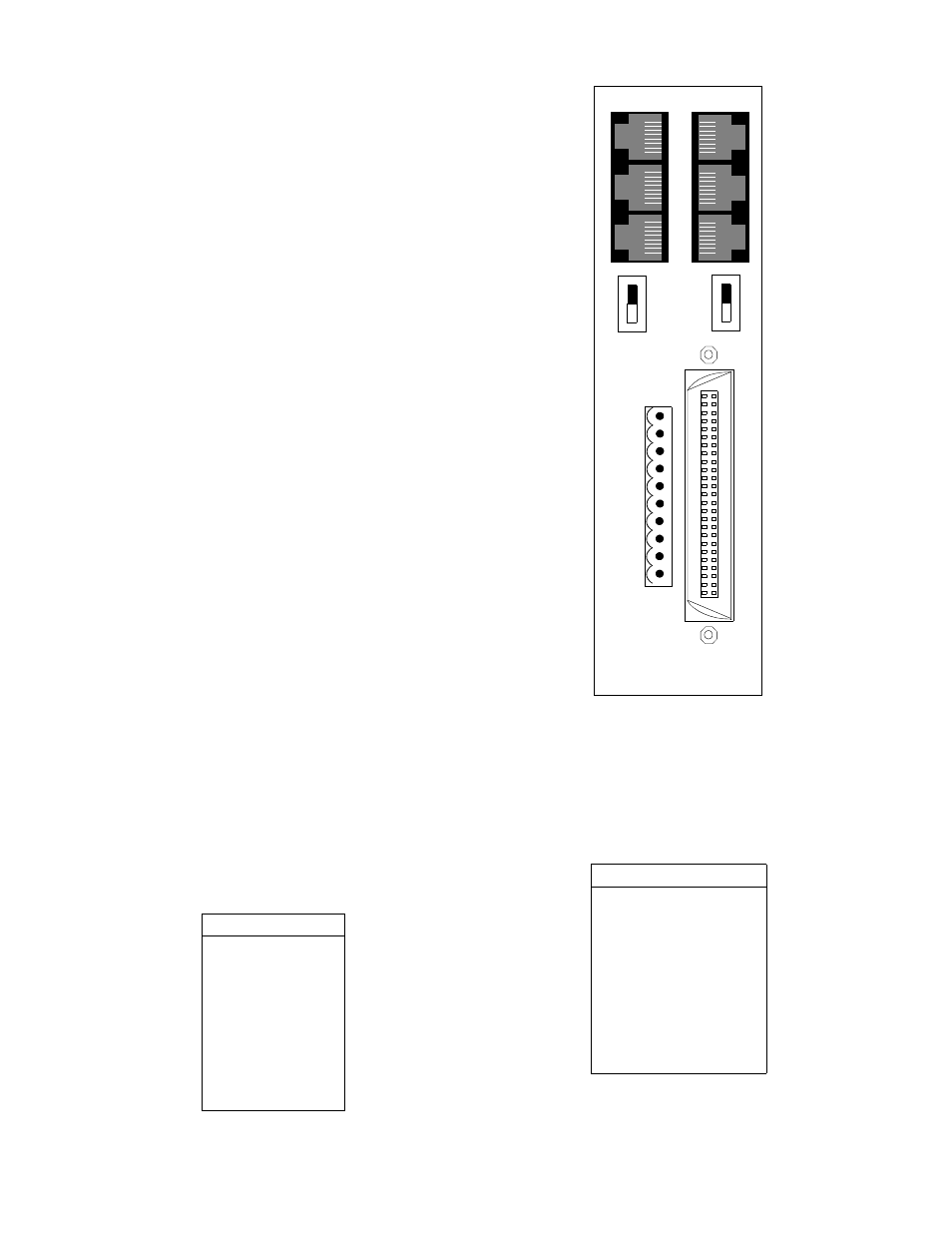
Port Connections
On the 1061, there are eight port connections located on the
rear panel as shown in (Figure 2-1). These ports are the
NMS, Expand, T1 In, T1 Multicast, and the Alarm/Power.
On the front panel, there is one port connection. It is the
supervisory port.
SUPV
The supervisory port, located on the front panel, allows you
to access the 1061 menu screens through a VT100 interface.
NMS (IN/OUT)
These two ports connect the 1061 to the TxPORT EM8000
and to other 1061 units in a daisy chain. Each unit in the
NMS chain must have a unique address, however, they all
use the same NMS bit rate.
Expand (A/B)
These two 8-pin modular jacks jump the
A
or
B
inputs
together providing additional input.
Table 2-B EXPAND Pinouts
Pin
EXPAND
1
Data Out
2
Data Out
3
Not Used
4
Data In
5
Data In
6
Not Used
7
Chassis Ground
8
Chassis Ground
T1 IN (A/B)
These two 8-pin modular jacks are used for the T1 input
signal as well as the output of each input. These two con-
nectors output AIS with no input.
Table 2-C T1 IN Pinouts
Pin
T1 IN
1
Data In
2
Data In
3
Not Used
4
Data Out
5
Data Out
6
Not Used
7
Chassis Ground
8
Chassis Ground
8
1
8
1
10
1
1
81
8
UNTERM
48 VDC
A
26
50
25
1
8
1
1
8
N
M
S
O
U
T
B
TERM
ALARM/
POWER
A
E
X
P
D
T1
A
-
I
N
N
M
S
I
N
B
E
X
P
D
T1
B
-
I
N
- - - - - - -
Figure 2-1 1061 Rear Panel
________