Tri Tool 642SB Clamshell Air and Hydraulic User Manual
Page 25
25
Model 642SB Low Profile Clamshell
92-0612 Rev. 131230
CAUTION:
CAUTION:
NOTE:
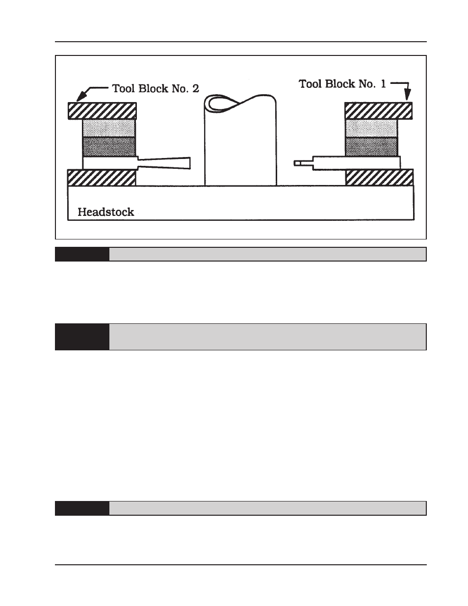
Either Tool Block may be designated as No. 1.
Position the Spacers flush with the inside face of the Tool Holder.
Position Tool Bits D and E approximately 1/2” (12.7 mm) outward from the cutting
edge of Tool Bit A.
Tool Bits D and E will be repositioned to contact the beveled surface as the
cutting
progresses.
Tighten the Set Screws holding Tool Bits A, D, and E.
Install the Tool Bits B and C into Tool Block No. 2 along with the two Spacers S1
and S2.
Position the Spacers flush with the inside face of the Tool Holder.
Tool Bits B and C should be the same distance inward from the Tool Holder.
Tighten the Set Screws holding Tool Bits B and C.
Set Tool Bit A to lead Tool Bit B and C by the desired land width as follows:
Make sure that the Tripper Shaft is in the ‘out’ position.
Rotate the Headstock slowly.
Tool Bit Set-Up