Tri Tool 230B Miter Mandrel User Manual
Page 14
14
TRI TOOL INC.
92-0841 : Rev. 050317
NOTE:
If the Mandrel Shaft is to be drawn directly toward one screw, the opposite
screw must be loosened far enough to allow for the take up before the near
screw is tightened.
Leave the Draw Nut slightly loose during and after the Angular Offset adjustment.
Check to see that the Adapter Plate Assembly is centered to the gimbal plate.
If not, locate the four (4) parallel offset adjustment screws and back off one
(1) or two (2) screws where the Adapter Plate Assembly is ‘in’.
Tightening to the opposite one (1) or two (2) screws will bring the Adapter Plate
Assembly toward the center.
To make the Parallel Offset adjustment, all four (4) screws must be slightly
loose.
Once the Adapter Plate Assembly has been roughly aligned and centered,
temporarily snug all of the Adjustment Screws and the Draw Nut.
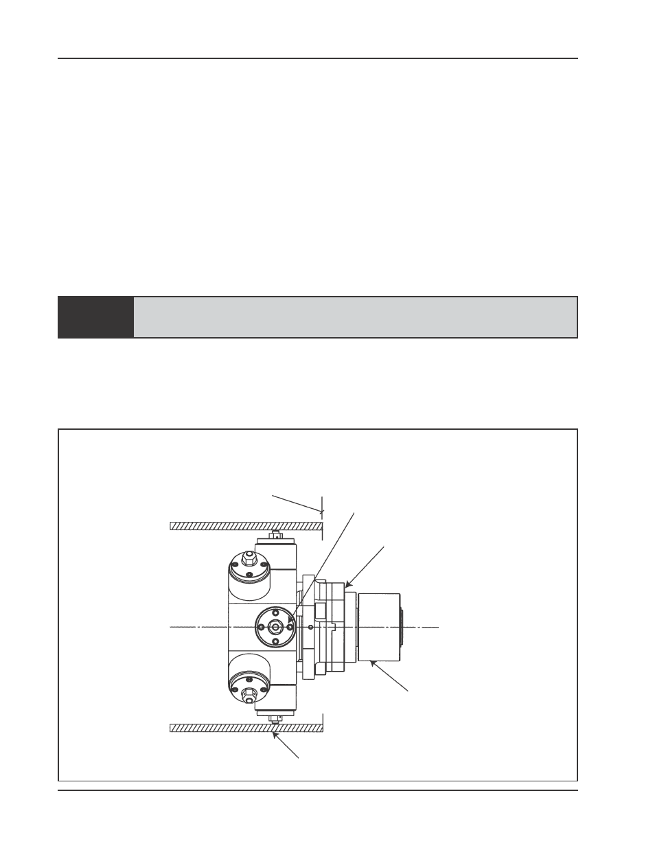
Insert the Miter Head into the workpiece.
Workpiece
Final Face Line
Angular Offset Pivot Point
Adapter Plate Assembly
Indicator Sleeve Assembly
Installation of the Indicator Sleeve Assembly