Tri Tool 230B Miter Mandrel User Manual
Page 12
12
TRI TOOL INC.
92-0841 : Rev. 050317
NOTE:
NOTE:
To make the Parallel Offset Adjustment, all four (4) screws must be slightly
loose.
Install the Mandrel Shaft Assembly onto the Adapter Plate Assembly and tighten the
draw rod to 250 ft/lbs (339 Nm) to 300 ft/lbs (407 Nm).
At this time, the Miter mandrel should feel absolutely tight and rigid.
Before installing the 230B BEVELMASTER™ be sure to read the Operator’s manual
carefully, giving special attention to all safety cautions and warnings.
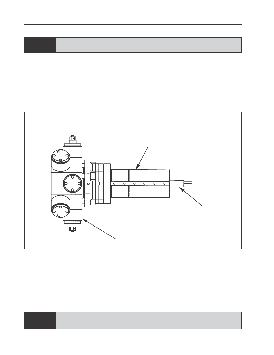
Mandrel Shaft Assembly and Draw Rod Locations
Mandrel Shaft Assembly
Miter Mandrel Head
Draw Rod
Check the gap between the Gimbal Plate and the Mandrel Head to see that it is
approximately even all around.
If it is not then loosen the angular offset adjustment screw(s) where the gap is
small and tighten the Angular Offset Adjustment Screw(s) where the gap is
wide.
Lightly tighten the Draw Nut.
All four (4) of the Angular Offset Adjustment Screws must be used in
conjunction with each other.