3 obstacles in the vessel – Tecfluid LU Series User Manual
Page 5

5
It is not desirable that the product reaches the instrument, because build-up can form on
the transducer, that would affect the measurement.
2.3
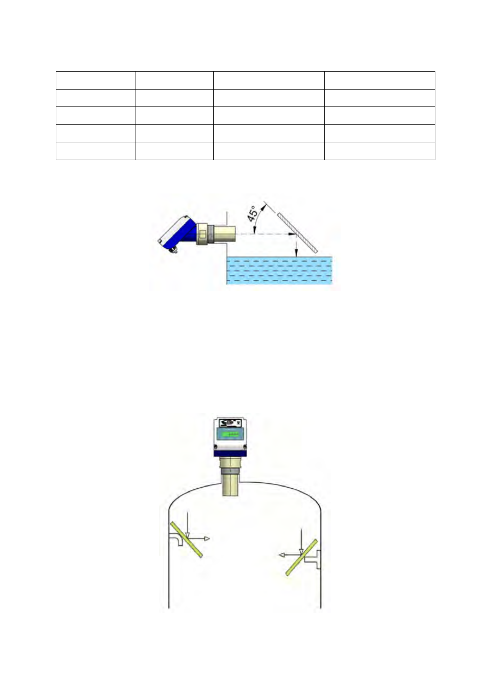
Obstacles in the vessel
The transmitter must be installed so that the ultrasonic beam can not find anything on its
path, as this could lead to unwanted echoes and incorrect measures.
In some cases, inclined reflectors can be placed in front of an obstacle, so that the beam
in this region is diverted and the reflected signal do not return to the instrument.
measured value, and the loop current will be 3.6 mA. or 22 mA depending on the
configuration (see section 5.9 in page 19).
Model
Dead zone
Max. distance (liquids)
LU91 / LU91H
0.3 m
6 m
LU93 / LU93H
0.45 m
12 m
Max. distance (solids)
3.5 m
7 m
LU923
0.45 m
10 m
5 m
LU921 / LU921H
0.3 m
5 m
2,5 m
In order to reduce the dead zone, a reflector can be installed as shown in the figure.
- AMD For 2000 Series (4 pages)
- AMO For 6000 Series (4 pages)
- AMR For 6000 Series (4 pages)
- AMM For 6000 Series (8 pages)
- LT-AMD (4 pages)
- TR420 (8 pages)
- AD Series (4 pages)
- TH6 For M21 Series (12 pages)
- TH5 For DP Series (12 pages)
- AMM For DP Series (8 pages)
- FLOMAT Series (12 pages)
- FLOMID-MX (20 pages)
- XT5D (24 pages)
- MX4H (24 pages)
- FLOMID Series (8 pages)
- MX4 For FLOMAT Series (56 pages)
- LC Series (4 pages)
- LC40 Series (8 pages)
- LC-40 ADF (4 pages)
- MX4 For FLOMID Series (64 pages)
- LD61 (8 pages)
- LD60 (8 pages)
- LD61N (8 pages)
- LD61R (12 pages)
- LP Series (12 pages)
- TR2420 (12 pages)
- LT-APR (4 pages)
- LTL-AMM (4 pages)
- LTL-APR (4 pages)
- LTL-ADF (4 pages)
- VH35 AISI-316 (4 pages)
- MC01 4-20 mA input (12 pages)
- MT-02 (9 pages)
- MT03L (32 pages)
- MT03F (40 pages)
- CH420L (8 pages)
- CH420R (12 pages)
- CH420P (12 pages)
- CIP (4 pages)
- CIP II (8 pages)
- DFD-2 E (8 pages)
- APTM44 (6 pages)
- CI-420 (8 pages)