Must, Temperature controller connection – TE Technology TC-36-25-RS485 User Manual
Page 32
32
Improper tuning of this temperature controller can lead to excessive thermal cycling and/or overheating
of the thermoelectric device, either of which are known to reduce the lifetime of any thermoelectric
device. Care should be taken to prevent the temperature of the TE device from going beyond the range
specified by the device manufacturer. Care should also be taken so that any thermal cycling of the TE
device is a result of changes in the controller’s set‐point temperature and not instability at a given set
point due to improper selection of the tuning variables.
3.1
Connect ONLY the TE device to the controller (fans should not be connected to the controller):
Positive TE device terminal to WP2
Negative TE device terminal to WP1
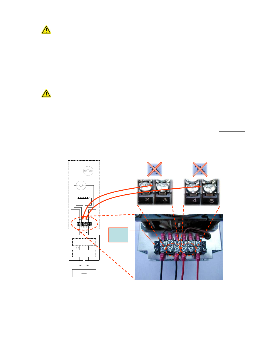
TE Technology’s standard thermoelectric cooling assemblies (TCA) have at least one fan on the heat sink.
The standard configuration has the thermoelectric modules and fan(s) wired to a terminal block with
jumpers across the terminals so that the fans and modules are connected in parallel. However, this
configuration is applicable only when applying power directly from the power supply. When using the TCA
with the temperature controller, the jumpers
MUST
be removed so that the controller is controlling
power only to the thermoelectric modules. There must be no electrical connection between the fans and
the modules; fans must be connected directly to the power supply, not to the controller. The controller
will be damaged if this is not followed. See the cooler manual for further details, but the picture below
shows the basic setup.
NOTE: Generally there is approximately a 0.5 to 1.3 V drop from the power supply to the TE device. You might
need to adjust the power supply accordingly to ensure full power is delivered to the TE device when needed.
Next, click the ON/OFF button in the OUTPUT section to turn on output power (again, make sure the set point
temperature is appropriate for the TE device before applying output power). The controller will begin to send
output power to the TE device.
Temperature Controller Connection
PROTECTION
DEVICES
DC POWER SUPPLY
THERMOELECTRIC
(PELTIER)
HOT-SIDE FAN
(ALL UNITS)
COLD-SIDE FAN
(AC-XXX UNITS ONLY)
TCA
TEMPERATURE
CONTROLLER
Terminal Block
Cover removed
for clarity. Re-
install before
operation.
Review electrical jumper connections. Remove electrical jumpers as required.