TE Technology TC-36-25-RS485 User Manual
Page 31
31
2.7.4 OVER CURRENT SET
This selects the level at which the over‐current protection for the TE device turns off the output power. This level
is adjustable in 2.5 A increments, and the allowable levels range from 0 A to 40 A. The controller will automatically
attempt to restart the output (either continuously or a fixed number of times) per the conditions set as described
in Section 2.7.5. During the restart attempts, the output will still be shut down each time if the over‐current level
is reached again. If a fixed limit of attempts is reached the output will be disabled until a “latch clear” signal is sent
(see Section 2.6.6) or the controller is turned off and then on again.
NOTE: THIS IS NOT AN ANALOG CURRENT LIMIT FEATURE!
The over‐current value is approximate; the actual current value the controller shuts off at may differ by 3 A or
more from the selected over‐current level. Also, it is normal to have an output current surge when the direction of
current flow is instantaneously reversed to a TE device that has a temperature difference established across it.
When this happens, the “apparent electrical resistance” of the TE device is lower because the Seebeck back‐
voltage does not immediately reverse polarity. The reversal of current will eventually reverse the temperature
difference across the TE device (and then its Seebeck back‐voltage will likewise change polarity). As the
temperature difference reverses, the current will revert back down to a steady‐state level.
2.7.5 OVER‐CURRENT RESTART ATTEMPTS / CONTINUOUS boxes
This sets the number of restarts the controller will attempt. Selecting the CONTINUOUS box provides an infinite
number of restarts. If a fixed limit of attempts is reached, the output will be disabled until a “latch clear” signal is
sent or the controller is turned off and then on again.
2.8
DISPLAY SECTION
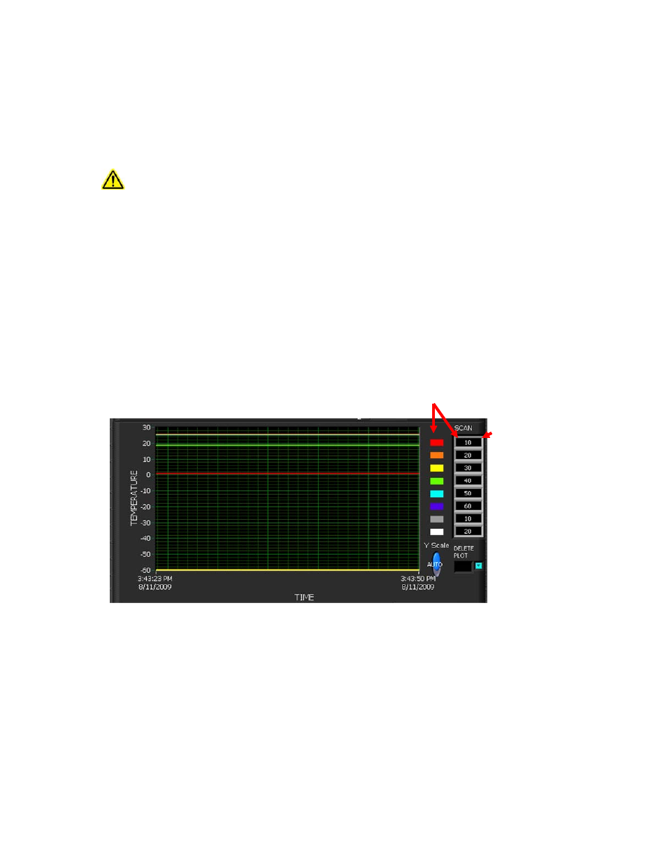
The DISPLAY SECTION contains the graphical display of samples taken of the controllers in the SCAN LIST. The
SCAN LIST contains the addresses of controllers to be sampled and is created by entering up to eight addresses
separated by commas. The PLOT LEGEND is automatically created from the SCAN LIST and depicts each controller
sampled with a different color. The graph is auto scaled ±10% of the minimum and maximum readings. More graph
options are available by right clicking on the graph.
3.0 FINAL SETUP—CONTROLLER TUNING
The tuning method follows the Ziegler‐Nichols closed‐loop tuning principals. The controller will first be set to a
high proportional bandwidth setting with no integral or derivative function (integral gain and derivative gain = 0).
Then, the bandwidth is gradually decreased until the temperature approaches set point and a small, sustained
oscillation in temperature is observed. The other tuning parameters are then readjusted based on the time period
of the temperature oscillation (natural period) and the proportional bandwidth needed to cause this oscillation.
CONTROLLERS
BEING SCANNED
COLOR OF CONTROLLER PLOT
CONTROLLERS
BEING SCANNED
COLOR OF CONTROLLER PLOT