TE Technology TC-36-25-RS485 User Manual
Page 22
22
2.2
CONTROL TEMPERATURE
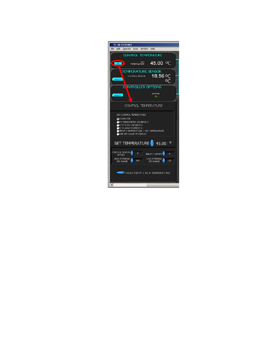
Click the SELECT button in the CONTROL TEMPERATURE section to display the CONTROL TEMPERATURE options.
2.2.1 SET CONTROL TEMPERATURE BY:
The CONTROL TEMPERATURE can be set by various methods, as described below. The set temperature value can
be anywhere within the range set in the EXTERNAL SET RANGE.
a) COMPUTER: This enables the controller to send a fixed percentage of output power. The values that can be
entered in the SET TEMPERATURE box range from –5.11 to +5.11. This corresponds linearly to a fixed percentage
of power output where –5.11 equals –100% power and +5.11 equals +100% power. If you selected HEAT WP+1
and WP2‐ in the OUTPUT section (See Section 2.7.1), then ‐5.11 corresponds to full‐power cooling. The value is
adjustable in 0.01 unit increments. See Section 2.5.1 for further details.
b) POTENTIOMETER ON INPUT 2: You can install a 5K ohm potentiometer on JP2 at pins 1, 2, and 3. The LOW
EXTERNAL SET RANGE temperature and the HIGH EXTERNAL SET RANGE temperatures are mapped to the full
counter‐clockwise and full clockwise positions of the potentiometer, respectively. The set temperature scales
linearly between 0 and 5K ohm set by the potentiometer.
c) 0 TO 5VDC ON INPUT 2: The set temperature can be changed by varying the voltage (up to 5 Vdc) applied across
JP2‐2(+) and JP2‐1(‐).
d) 0 TO 20mA ON INPUT 2: The set temperature can be controlled using a 20 mA current source. A 249 ohm resistor
should be applied across pins JP2‐1 and JP2‐2.
e) INPUT 2 TEMPERATURE + SET TEMPERATURE: This can be used to maintain a constant temperature difference
relative to the secondary thermistor. The secondary thermistor is installed at JP2‐1, 2.
f) USE SET VALUE OF DISPLAY: The buttons on the optional, MP‐2986 Keypad and Display Accessory are used for
changing the set point temperature. The display must be enabled in order to use this feature (see Section 2.4.2).