Super Systems Compact HMI User Manual
Page 15
Compact HMI and Compact HMI Editor Operations Manual
Super Systems Inc.
Page 15 of 60
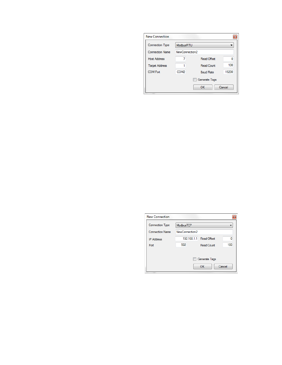
For ModbusRTU Connections
(Example: Figure 13)
• Host Address: The address of the
touch screen. Normally, this setting
can be kept as the default.
• Target Address: The address of the
data device. Normally, this setting can
be kept as the default.
• COM Port: The COM (serial) Port with
which the Compact HMI touch screen
will be connected to the data device.
This must match the actual COM Port
on which the serial cable is connected
to the touch screen.
The default COM Port is COM 2. Some
touch screens may have only one COM
Port. In such a case, COM 1 will need
to be used for the data device
connection, and an Ethernet
connection will need to be used for the
SSi 9000 Series controller.
• Read Offset: The register address
where Compact HMI starts reading.
This must be defined to the word level
within the data device.
Figure 13 – New Connection window (ModbusRTU)
• Read Count: The default number of registers,
starting with the Read Offset, that will be read.
The default is 100. This value must not exceed
the number of registers actually defined within
the data device.
• Baud Rate: The rate (in units per second) at
which communications bits are sent between
the touch screen and data device. The default is
19200.
Generate Tags checkbox: When checked, this
checkbox will cause tags to be generated. The tags
generated will be based on the Read Offset and
Read Count defined in this menu. For example, if
the Read Offset is 0 and the Read Count is 100, the
tags generated will be named Tag0, Tag1, and so
on, through Tag99.
For ModbusTCP Connections
(Example: Figure 14)
• IP Address: The IP address of the data
device.
• Port: The port number on the data
device through which the data device
will exchange data.
• Read Offset: The register address
where Compact HMI starts reading.
This must be defined to the word level
within the data device.
• Read Count: The default number of
registers, starting with the Read
Offset, that will be read. The default is
100. This value must not exceed the
number of registers actually defined
within the data device.
Figure 14 – New Communications Window (ModbusTCP)
• Generate Tags checkbox: When checked, this
checkbox will cause tags to be generated. The
tags generated will be based on the Read
Offset and Read Count defined in this menu.
For example, if the Read Offset is 0 and the
Read Count is 100, the tags generated will be
named Tag0, Tag1, and so on, through Tag99.