Dip switch settings – Super Systems H2 Sensor User Manual
Page 5
Hydrogen (H
2
) Sensor Operations Manual
Super Systems Inc.
Page 5 of 17
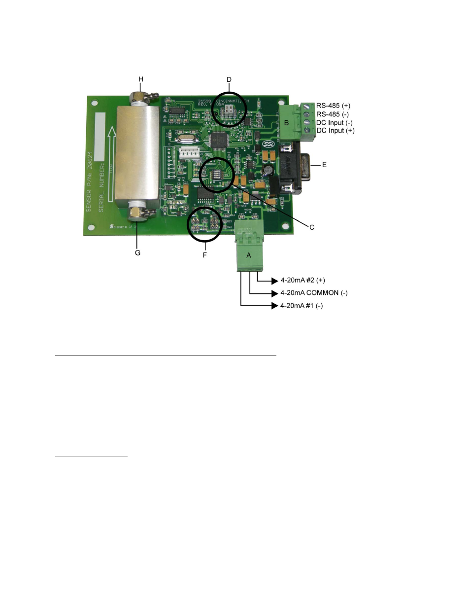
Wiring:
Figure 2 - H
2
Sensor Wiring
Switch Settings, Jumper Settings, and Connector Assignments
Location of RS-485, DC Input, and Analog Output Terminals
(Items “A” and “B” in Figure 2)
There are two terminal blocks on the H
2
cell circuit board. Figure 2 shows their locations.
One block (“A”) contains the analog output terminals. Jumper settings on the circuit board are
used to change whether resistance or voltage is generated. These jumper settings can be found
in “Analog Output Jumpers” below.
Another block (“B”) contains the digital communications (RS-485) and power (DC) terminals.
Dip Switch Settings
(Item “C” in Figure 2)
The first three dip switches determine the Modbus address. The address can be set for any
number between 1 and 8 using a binary numbering system where Bit #1 is the least significant
bit and Bit #3 is the most significant bit. The diagram below describes the switch position for
each possible address. The shaded area indicates the location of the switch.