Sensor output configuration, Sensor output calibration – Super Systems H2 Sensor User Manual
Page 10
Hydrogen (H
2
) Sensor Operations Manual
Super Systems Inc.
Page 10 of 17
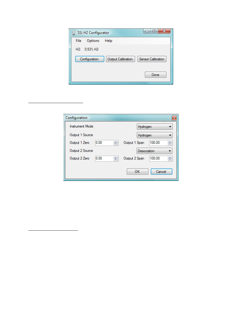
Figure 9 - Overview screen
Sensor Output Configuration
The Configuration screen (Figure 10) allows basic configuration of the H
2
cell.
Figure 10 - Configuration screen
The Instrument Mode is the primary PV (Process Variable) setup. This is mainly used by the
touch screen and normally does not need to be changed as the % H
2
is always available. The
output sources are the PVs that will be retransmitted via the selected output. The Output Zero
is the PV value that will result in a 4 mA output and the output span value is the PV value that
will result in a 20 mA output.
Sensor Output Calibration
Output calibration calibrates the outputs. Each output can be zeroed and spanned. To perform
this calibration a reliable measurement device capable of accurately measuring a 4-20mA
signal will be required. An example screen is shown in Figure 11; a screen showing the success
of an output calibration can be seen in Figure 12.