Sundance SMT784 User Manual
Page 24
User Manual SMT784
Page 24 of 31
Last Edited: 19/03/2009 14:12:00
In this instance, the first
writeword
places the ADC FIFO’s in reset and configures
the
0x1C
register to return register contents information to the Host when a
readword
is performed. The looped
readword
command empties samples remaining
in the FIFO, and the final
writeword
configures the SMT784 to send samples from
channels A and B in straight binary format to the Host.
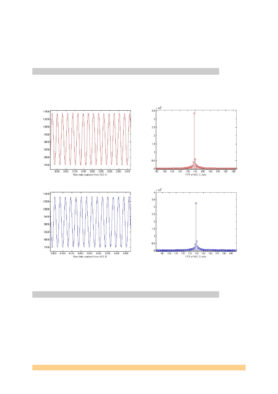
7.3 Viewing the Samples
By using the provided MATLAB script “ANALYSIS.m”, the samples stored on the text
files may be viewed. The following is a zoomed in view of a test run using channels
C and D with a 2MHz analogue signal sampled at 33Mhz and a 4096-point FFT.
Figure 8 ANALYSIS.m
7.4 Uploading Firmware to Flash
A good guide for how Sundance firmware is typically modelled can be found in the
SMT6500 .chm help files.
The firmware provided may be updated from time to time or can be modified as
desired to implement different functionality into the FPGA. For example, data flow
can be stored in DDR memory, output to the SATA connection, SHB, Ethernet, Fibre
transceiver, etc.
The PCI/PCIe controller for the SMT784 is in a VHDL wrapper within the Virtex5
FPGA. The SMT6002 Flash Utility can access the system’s flash either through this