3 smt399-160 characteristics, 4 power supply structure, Smt399-160 characteristics – Sundance SMT399-160 User Manual
Page 10: Power supply structure, Figure 3 - output main characteristics
DDS outputs are doubled and combined with Variable Gain Amplifiers (VGA).
Analog signals are all single-ended and output on MMBX connectors (J13, J14, J15 and J20)
for connection to a 50-Ohm load.
Output Sine waves can be turned into ‘sharp’ square signals using the AD9954 built-in
comparator. Square signals (one per DDS) are also available on MMBX connectors (J24 and
J25) on LVTTL format.
All DDS settings travel via the FPGA present on SLB base module. Information comes from a
Comport and the FPGA stores it first into internal registers and interfaces it to the DDS chips
via the SLB connector. Comports follow the Texas Instrument C4x standard.
4 green LEDs are also available and driven by the FPGA to report working or failing
conditions to the user. Other green LEDs show that all power supplies are ON and working.
Two external triggers (J11 and J23) are also available.
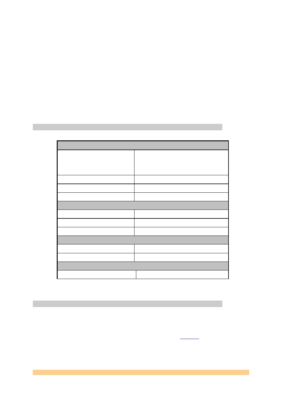
4.3 SMT399-160 characteristics.
Analog Outputs (J13, J14, J15 and J20).
Analog Output Voltage Range
0 to 2.12 Volts without saturation (sine wave)
0 to 3.0 Volts with saturation
(Output level set via Control Register - VGA)
Output Impedance
Terminated to be connected to a 50-Ohm load.
Frequency range
Up to 160 MHz
Frequency resolution
0.0931 Hz
Square Outputs (J24 and J25).
Output Format
LVTTL
Frequency range
Up to 160 MHz
Frequency Resolution
0.0931 Hz
External Triggers (J11 and J23).
Input Range
LVTTL (default FPGA PAD setting)
Frequency Range
Up to 160 MHz
Input Reference (Option – J21)
Frequency range
0 to 400 MHz.
Figure 3 - Output main characteristics.
4.4 Power Supply structure.
The SMT399-160 conforms to the TIM standard for single width modules. The TIM
connectors supply 5 Volts to the base module, which also requires an additional 3.3-Volt
power supply, which must be provided by the two diagonally opposite mounting holes. This
3.3-volt is present on all Sundance TIM carrier boards. From these two power rails, are
generated a filtered 3.3-volt as well as a 1.8-volt
s.
Greens LEDs placed on the board report the state of the power supplies.
The SMT399-160 requires 2 power rails from the SLB power connector: +3.3 and +5 Volts.
User Manual SMT399-160
Page 10 of 39
Last Edited: 24/05/2007 17:12:00