Dac control – dac output, Dac control – load srg0 and srg1 – minimum value, Figure 5 - control register – Sundance SMT377 User Manual
Page 18
Version 1.1
Page 18 of 22
SMT377 User Manual
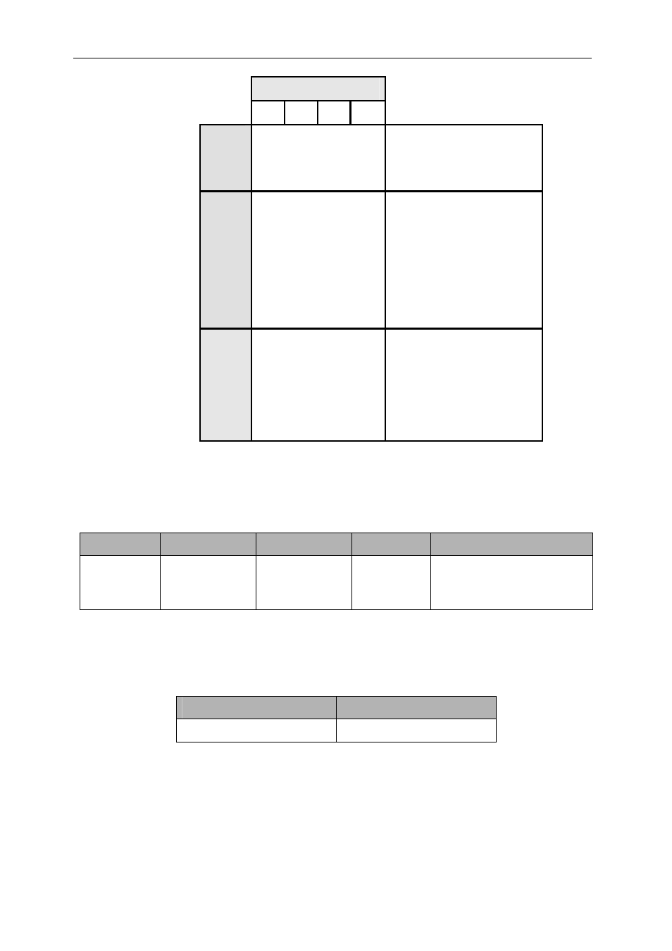
Figure 5 - Control register.
Control bits
31 30 29 28
0 0 0 0
DAC
output
DAC
control
0
0
0
1
Load SRG0 and SRG1
0 1 0 0 Load
Start
Address
0 1 0 1
Size
burst
0
1
1
0
Load Data for Memory
Memory co
ntrol
0 1 1 1
Read from Memory
(address)
1 0 0 0 Start
Pattern
generator
1 0 0 1 Stop
Pattern
generator
Miscella
neous
1 1 1 1 Internal
register
Reset
Bits 31-28 determine the function of the bits 27-0. Here is the detail of all the
functions available to control the SMT377.
DAC Control – DAC output.
27…21
20
19
18…16
15…0
Not used
Quick Load –
Ch. 4,5,6 and 7
Quick Load –
Ch. 0,1,2 and 3
Channel
number
(000-111)
Sample Data
Note: Quick Load, means that the DAC output value of the current control word will
be loaded into four or eight channels at the same time. In the case of a quick load,
bits 16 to 18 are ignored.
DAC Control – Load SRG0 and SRG1 – minimum value 200.
27…14
13…0
SRG1 SRG0
Each Shift Register is 14-bit wide. The sampling clock is derived from an internal
20MHz (20,000KHz) clock and the value of the shift register is the divider. The
minimum value is 200 (matching with the maximum sampling frequency if the DAC –