Sundance SMT370v2 User Manual
Page 39
Version 2.0
Page 39 of 46
SMT370v2/v3 User Manual
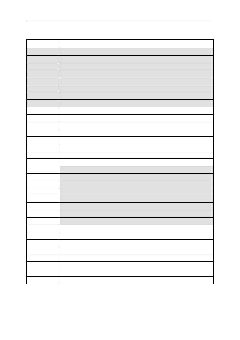
Register 0x7 – DAC control – Pattern generator.
Bit number
Description
Bit 31
0
Bit 30
1
Bit 29
1
Bit 28
1
Bit 27
External Trigger Level (‘0’=Active low; ‘1’=Active high)
Bit 26
External Trigger Enable (‘0’=External Trigger Disabled; ‘1’=Enabled)
Bit 25
Channel B Enable (‘0’=Disabled; ‘1’=Enabled)
Bit 24
Channel A Enable (‘0’=Disabled; ‘1’=Enabled)
Bit 23
Bit 22
Direct Transfer (‘1’ = SHB Direct To DAC mode; ‘0’ = Pattern generator mode)
Bit 21
Start/Stop Pattern generator (‘1’ = Start; ‘0’=Stop)
Bit 20
Load Pattern Size (Active high - ‘1’ = Load into FPGA; ‘0’= No Load)
Bit 19
Pattern Size – Bit 19.
Bit 18
Pattern Size – Bit 18.
Bit 17
Pattern Size – Bit 17.
Bit 16
Pattern Size – Bit 16.
Bit 15
Pattern Size – Bit 15.
Bit 14
Pattern Size – Bit 14.
Bit 13
Pattern Size – Bit 13.
Bit 12
Pattern Size – Bit 12.
Bit 11
Pattern Size – Bit 11.
Bit 10
Pattern Size – Bit 10.
Bit 9
Pattern Size – Bit 9.
Bit 8
Pattern Size – Bit 8.
Bit 7
Pattern Size – Bit 7.
Bit 6
Pattern Size – Bit 6.
Bit 5
Pattern Size – Bit 5.
Bit 4
Pattern Size – Bit 4.
Bit 3
Pattern Size – Bit 3.
Bit 2
Pattern Size – Bit 2.
Bit 1
Pattern Size – Bit 1.
Bit 0
Pattern Size – Bit 0.