Tim connectors’ position – Sundance SMT358 User Manual
Page 22
Version 2.5
Page 22 of 25
SMT358 User Manual
Figure 9 shows the Physical Layout of the SMT358, indicating the external
connectors with their location and numbering.
Connector definitions are as follows:
SDB
A,B,C,D
: Digital Data & Clock Input /Output Signal – Sundance Digital Bus High
Density ODU connector A (40-way High Density IDC Connectors).
JTAG
: JTAG Signals – 6-way connector.
P1 :
Top
Primary
connector.
P2
: Bottom Connector. (Bottom Primary and Global Expansion Connectors)
Table 2: SMT358 connector reference table
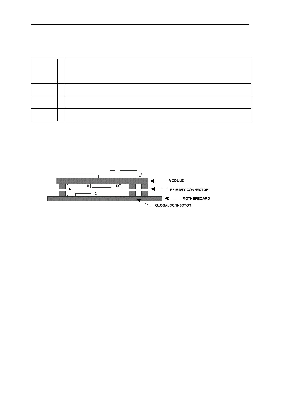
TIM Connectors’ Position
Figure 10: Tim Connectors’ position
See also other documents in the category Sundance Equipment:
- SMT107 (16 pages)
- SMT6035 v.2.2 (39 pages)
- SMT6012 v.4.6 (22 pages)
- FC100 (12 pages)
- FC108 v.1.1 (10 pages)
- SMT6065 v.4.0 (45 pages)
- FFT v.2.1 (19 pages)
- SMT111 (18 pages)
- SMT118LT (10 pages)
- SMT118 (20 pages)
- SMT123-SHB (13 pages)
- SMT128 (15 pages)
- SMT145 (18 pages)
- SMT148 (35 pages)
- SMT130 v.1.0 (46 pages)
- SMT148FX (48 pages)
- SMT310Q (55 pages)
- PARS (70 pages)
- SMT166-FMC (52 pages)
- SMT166 (44 pages)
- SMT300Q v.1.6 (61 pages)
- SMT310 v.1.6 (50 pages)
- SMT317 (24 pages)
- SMT326v2 (24 pages)
- SMT338 (19 pages)
- SMT349 (32 pages)
- SMT339 v.1.3 (27 pages)
- SMT338-VP (22 pages)
- SMT351T (37 pages)
- SMT351 (25 pages)
- SMT350 (45 pages)
- SMT362 (30 pages)
- SMT365G (23 pages)
- SMT364 (37 pages)
- SMT373 (15 pages)
- SMT368 (24 pages)
- SMT370v3 (46 pages)
- SMT377 (22 pages)
- SMT381 2007 (31 pages)
- SMT381-VP (81 pages)
- SMT387 (42 pages)
- SMT391 (18 pages)
- SMT384 (47 pages)
- SMT390-VP (55 pages)