Power supply – Sundance SMT118 User Manual
Page 5
Version 1.0
Page 5 of 20
SMT118v2 User Manual
Power Supply
Power is supplied to the SMT118 via the 4 pin connector HDR9 (referring to
connector position section, HDR9 is located at the top right of the drawing). A
minimum current of 200mA is required by the circuitry of the SMT118. The maximum
current will be dependant on other TIMs mounted on the SMT118.
The on-board supplies are generated by custom designed industry standard pin-
compatible 2” x 1” DC-DC converters. The 12V module is based around the
device and includes an input voltage regulator to allow a maximum of an 18V
input. The 5 and 3.3V supplies are based around the
device and these
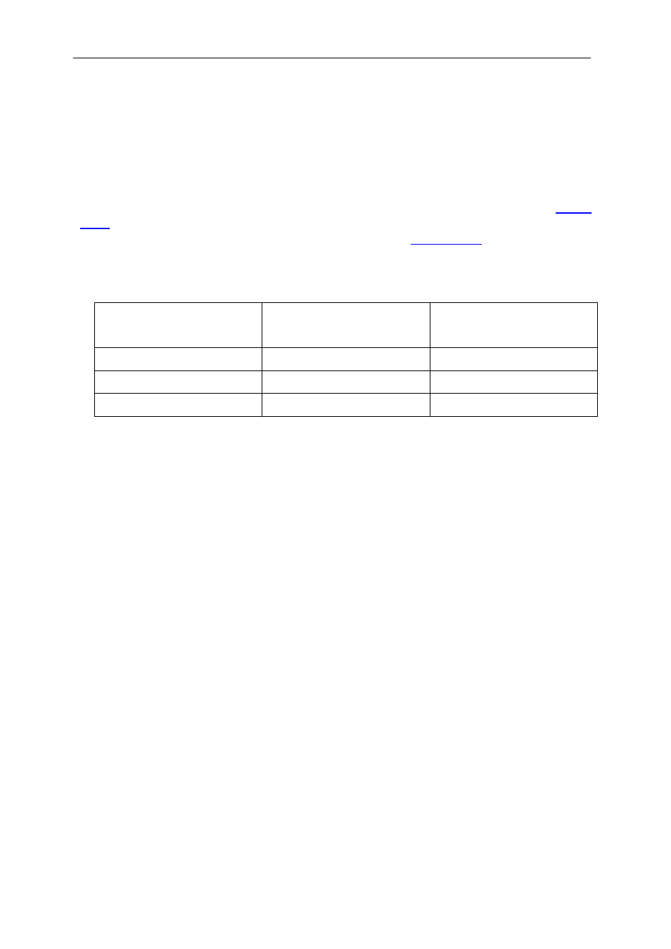
allow an input range from Vout+1.5 to 30V. The individual supplies are rated as
follows:
Voltage rail
(Volts)
Minimum input
(Volts)
Max current delivery
(Amps)
3.3 4.5 5
5.0 6.5 5
12.0 7.0 1
These values imply a minimum board supply of 7.0V. The maximum input is 18.0V.
Note that a –12V supply is not provided as standard, but an option is available to use
a dual output 12 or 15 volt DC-DC converter which will be able to supply both positive
and negative supplies to the TIM sites. When this option is installed the board supply
voltage must be greater than 10V.
Individual LEDs are illuminated when each of the DC-DC converters becomes active.