Memory map, Board size, Memory map board size – Sundance SMT118 User Manual
Page 12
Version 1.0
Page 12 of 20
SMT118v2 User Manual
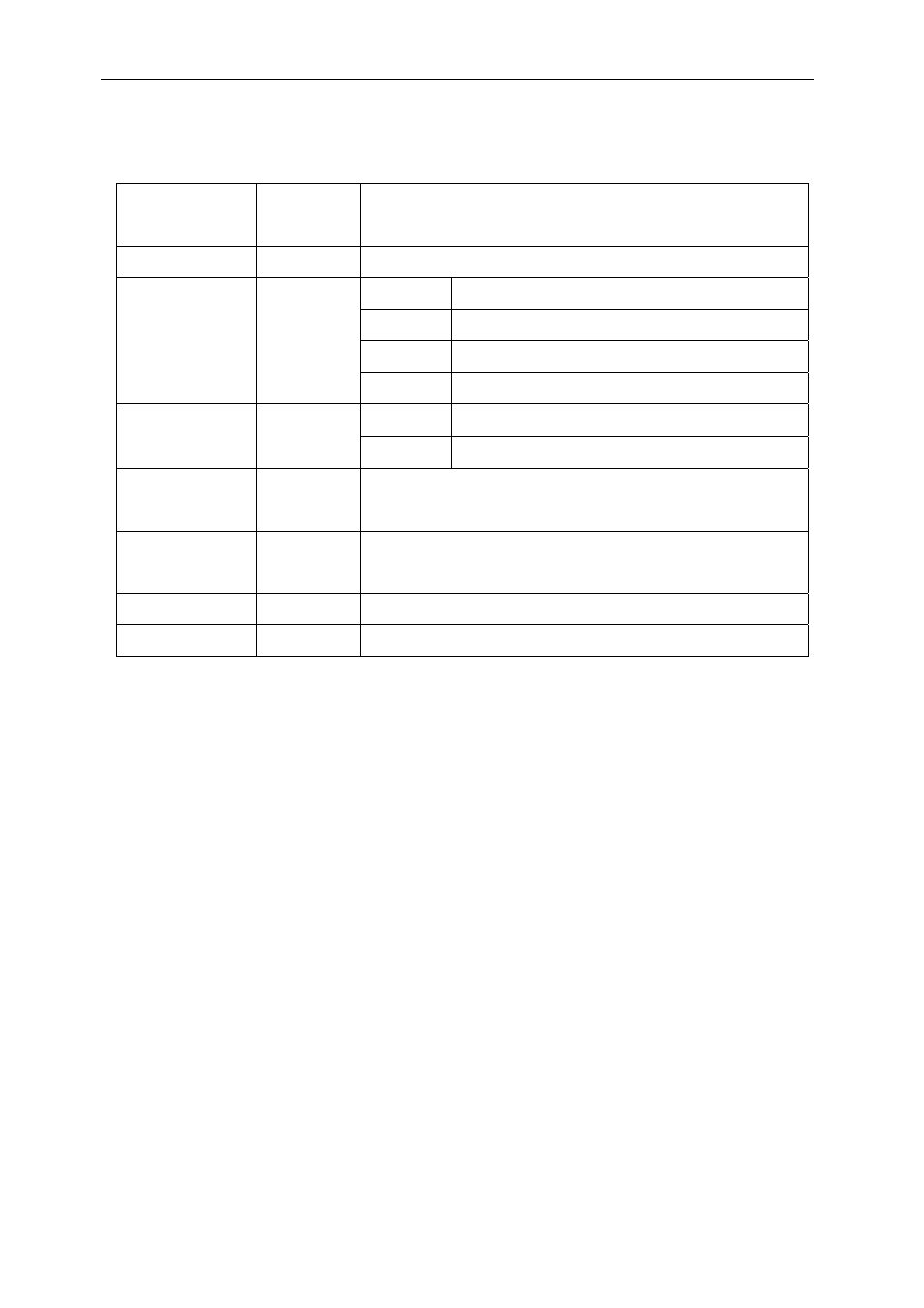
Memory Map
Address
(hex)
Resource Comment
F8000000
Flash
Can be accessed as 8 or 32-bit words. See CSR.
UART1
F9000000 - F9000007
UART2
F9000008 - F900000F
UART3
F9000010 - F9000017
F9000000 QUART
UART4
F9000018 - F900001F
Control
FA800000 (0=input, 1=output)
FA000000 TTL
I/O
Data FA000000
FB000000
LEDs
Data bits 0-3 set to illuminate respective LED.
Data bits 4-7 correspond to the off-board LEDs.
FC000000
CSR
Bit 0 clear to select 8-bit flash mode.
Bit 0 set to select 32-bit flash mode.
FD000000
ICR
Interrupt control register. See interrupt section.
FF000000
ISR
Interrupt status register. See interrupt section.
Board Size
The physical size of the board is 145mm x 210mm.
Using a standard IDC connector (with strain relief) inserted onto the SMT366, which
is then mounted onto the SMT118, will produce a component height of 24mm above
the top surface of the board.