Sumix SMX-M7xx User Manual
Page 86
Trigger Connector
86
SMX-M7x Series USB2.0 Camera User Guide
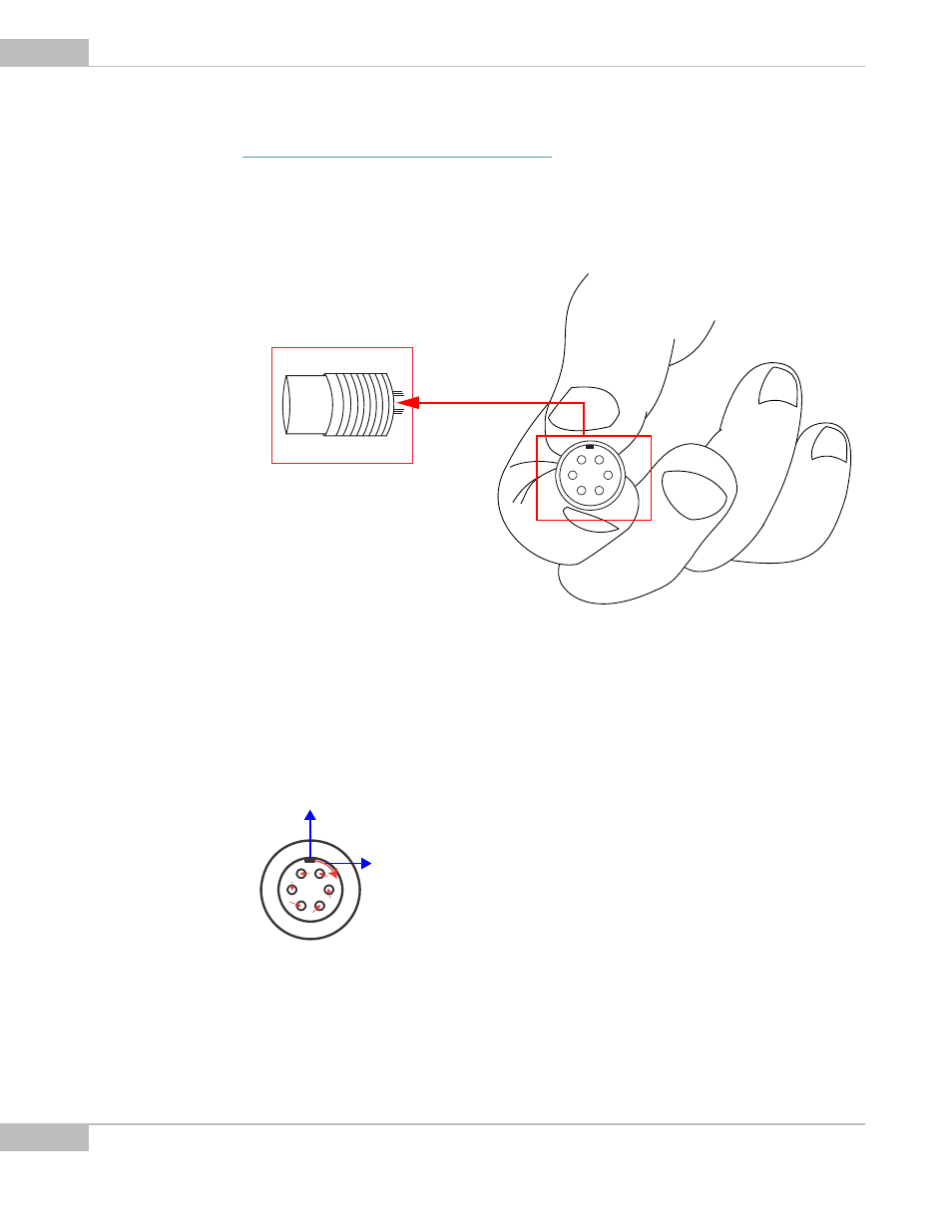
Please note that each pin is marked with a number according to the pin layout (see
“Soldering of Connector with Cable” on page 77
). The pins numbering is located at the
internal side of the inner part of the connector.
Figure 9-15 Connector pinout outlook
Note also that direction of pin numbering is done clockwise starting from the key at the
upper edge of the inner part of the connector.
Figure 9-16 The pin numbering direction
When the soldering is done, insert the inner part of the connector in the main part.
1
2
3
4
5
6
1
2
3
4
5
6
Key: the start point of pin num-
bering
Shows the direction of pin
numbering