Studio Technologies 230 2008 User Manual
Page 25
Model 230 User Guide
Issue 7, October 2008
Studio Technologies, Inc.
Page 25
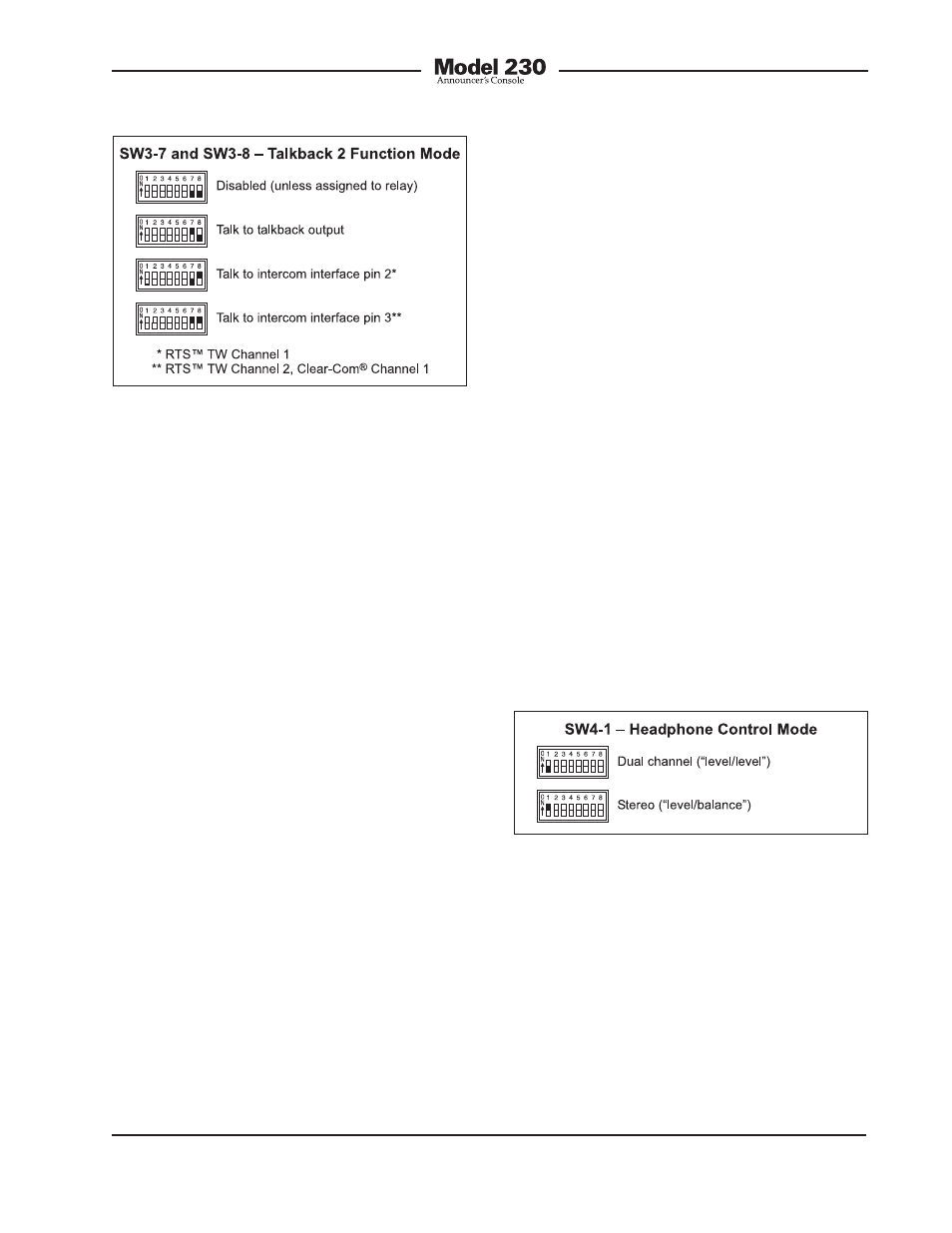
Four modes are available:
• Disabled: In this mode the talkback 2
button is disabled. The exception is if
the auxiliary relay is configured to follow
the status of talkback button 2. In this
case the button will control the relay;
no other functions will be impacted.
• Talk to talkback output: In this mode the
talkback 2 button will control the routing
of audio to the line-level talkback output.
• Talk to intercom interface pin 2: In this
mode the talkback 2 button will control
the routing of talkback audio to pin 2 of
the intercom interface. Pin 2 is channel 1
of an RTS TW intercom system.
• Talk to intercom interface pin 3: In this
mode the talkback 2 button will enable
the routing of talkback audio to pin 3 of
the intercom interface. Pin 3 is channel
2 of an RTS TW intercom system. For
a single-channel Clear-Com intercom
system it will be channel 1.
Headphone Output Operating Modes
The user is provided with two rotary level
controls (“pots”) that are associated with
the headphone output. Switches SW4-1,
SW4-2, and SW4-3 are used to configure
the way the controls function. With just
these three switches a wide range of oper-
ating modes can be configured. Carefully
reviewing the capabilities of the available
functions may prove worthwhile.
Dual-Channel or Stereo Mode
Switch SW4-1 is used to select whether
the controls provide a dual-channel
(“level/level”) or stereo (“level/balance”)
mode of operation. In the level/level mode
the two controls operate independently,
each controlling the level of one of the
headphone output channels. This mode
is generally used for on-air broadcast
applications where independent cue
signals are provided to the left- and
right-headphone channels. In the level/
balance mode the left control sets the
overall output level for both headphone
channels. The right control is used to ad-
just the balance (the relative levels) of the
left and right channels. This mode is gen-
erally best suited for applications where a
stereo cue source is being provided.
Figure 14. Headphone control mode settings
Figure 13. Talkback output 2 function mode
settings
Reverse Left/Right Mode
Switch SW4-2 is used to select whether the
rotary controls are in the normal or reverse
left/right mode of operation. When selected
to the normal mode, and level/level mode
is also selected, the left control adjusts the
level of headphone output’s left channel.
(This is the signal that appears on the tip
lead of the ¼-inch 3-conductor jack.) The
right control adjusts the level of the right