Headphone source selection – Studio Technologies 230 2008 User Manual
Page 20
Issue 7, October 2008
Model 230 User Guide
Page 20
Studio Technologies, Inc.
could occur with special Model 230 appli-
cations. But with a microphone connected
as the input source one should never use
the 0 dB setting. The issue is that with no
gain added to the microphone input sig-
nal, the relative noise floor on the circuitry
associated with the main output and
talkback functions will be much too high.
These circuits are designed for handling
line-level signals, expecting to receive
audio from the output of the microphone
preamplifier. In conclusion, the 0 dB gain
setting doesn’t highlight a problem, but
simply reflects the unit’s gain structure.
Phantom Power On/Off
The Model 230 can provide nominal 48
volt phantom power to the microphone
input. Switch SW1-8 controls whether or
not phantom power is active. By phantom
power’s very nature it could be left applied
to the microphone input at all times. But
generally people prefer to turn it off unless
required for a specific microphone.
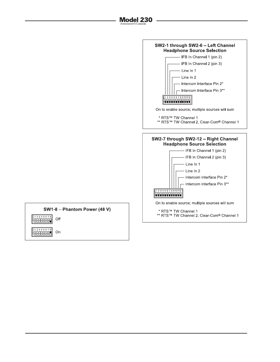
Figure 6. Left and right channel headphone
source selection settings
Figure 5. Phantom power switch settings
Headphone Source Selection
Switch assembly SW2 is used to config-
ure the source or sources that are routed
to the stereo headphone output. The six
headphone sources are IFB channel 1,
IFB channel 2, line input 1, line input 2,
intercom channel 1, and intercom channel
2. The IFB channels are provided by way
of the IFB input connector located on the
Model 230’s back panel.
The line inputs are connected using two
connectors also located on the back pan-
el. Associated with line inputs 1 and 2 are
level trim potentiometers. They are pro-
vided so that audio sources with a wide
range of nominal levels can be effectively
used as cue sources. Please refer to the
Advanced Operation section of this user
guide for details on using the trim pots.
Audio associated with intercom channels
1 and 2 is provided by way of the intercom
interface whose connector is also located