Configuration, Configuration, Microphone preamplifier gain and phantom power – Studio Technologies 230 2008 User Manual
Page 18
Issue 7, October 2008
Model 230 User Guide
Page 18
Studio Technologies, Inc.
computer to create the desired text. The
finished label size should be 0.625-inches
(15.8 mm) square. The completed art-
work can then be printed on transparency
film sheets using a laser or inkjet printer.
These sheets are readily available from
most office supply stores. A pair of scissors
or an X-ACTO® knife will complete the task.
Configuration
For the Model 230 to support the needs
of specific applications a number of operat-
ing parameters must be configured.
These include microphone preamplifier
gain, phantom power on/off, headphone
source and output mode selection, and
operating modes. One 12-position and
three 8-position DIP-type switch assemblies
are used to establish the desired configura-
tion. These switch assemblies are referred
to as SW1 through SW4, with individual
switches designated as SW1-1, SW1-2,
etc. The switch assemblies are accessed
through openings in the bottom of the
Model 230’s enclosure. The enclosure
does not have to be disassembled to gain
access to the switches.
To prevent unauthorized personnel from
changing the configuration settings, a
security plate is attached to the bottom
of the Model 230’s enclosure. For conve-
nience, attached to the security plate is a
configuration settings label. It provides a
summary of the configurable parameters
and related information. Refer to Appendix
A for a representative view of the label. The
security plate is held in place by means
of four rubber bumpers (“feet”) that have
built-in screws. Using your fingers, remove
the four bumpers so that the plate can be
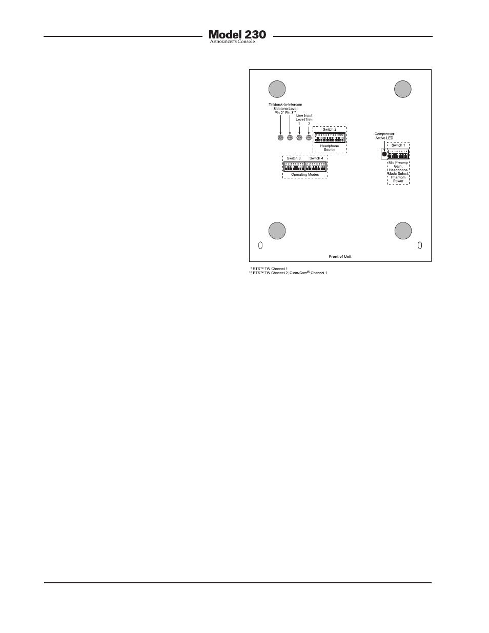
removed. Refer to Figure 3 for a detailed
view of the configuration switch assemblies.
Figure 3. Bottom view of Model 230 showing
configuration switches, trim pots, and
compressor active LED
Microphone Preamplifier Gain
and Phantom Power
Five switches are used to set the gain of
the microphone preamplifier. One switch is
used to select the on/off status of the phan-
tom power supply.
Microphone Preamplifier Gain
Switches SW1-1 through SW1-5 are used to
select the gain of the microphone preampli-
fier. The choices are 20, 30, 40, 50, and 60
dB. Only one switch should be enabled at a
time. There’s no problem changing the gain
setting while the unit is operating. Audio
clicks or pops might occur during gain tran-
sitions, but this shouldn’t be a major issue
as long as associated monitor loudspeakers
are temporarily attenuated or muted.
Selecting the correct amount of gain for an
application might take a little experimenta-
tion. The goal is to bring the microphone’s