Headphone output—right channel status – Studio Technologies 230 2008 User Manual
Page 22
Issue 7, October 2008
Model 230 User Guide
Page 22
Studio Technologies, Inc.
please review the block diagram located
at the end of this user guide.
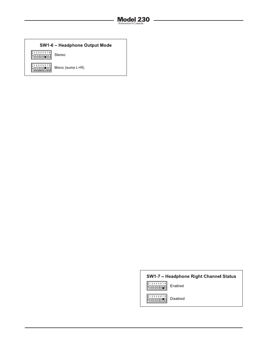
Headphone Output—Right
Channel Status
Switch SW1-7 allows the right channel
of the headphone output to be disabled.
This is provided for applications where
monaural headsets or headphones are
going to be connected. In general, mon-
aural devices use 2-channel (tip and
sleeve) ¼-inch plugs. When inserted into
the Model 230’s stereo (3-conductor)
headphone output jack the right channel,
electrically connected to the jack’s ring
lead, will be shorted. While this condition
should not damage the output circuit, it
will cause current to flow unnecessarily.
To minimize this possibility disable the
right channel output by placing switch
SW1-7 to its on position.
It’s important to note that the circuitry
that disables the right channel is electri-
cally just prior to the right channel output
circuit. It is after (“post”) all other circuitry,
including the source assignment DIP-
type switch, level controls, and monaural
function. It will not impact normal use of
the other functions, including the ability to
create the special “2-channel headphone
mix” mode previously discussed. For
signal-flow clarification please review the
block diagram located at the end of this
user guide.
Figure 8. Headphone output—right channel
status settings
Figure 7. Headphone output mode settings
left- and right-channel headphone output
driver circuits. The outputs of these cir-
cuits connect, by way of 51 ohm series
protection resistors, to the headphone
output jack.
The headphone output monaural mode
feature was specifically included so that
a special “2-channel headphone mix”
mode can be created. By enabling the
mono mode, the two front-panel user level
controls (“pots”) can be used to create
the desired “mix” of signals being sent
to the headphone outputs. Many, many
applications, especially in production
settings, can benefit from this capability.
The desired cue sources must be carefully
assigned to take advantage of the monau-
ral mode. The first cue source should be
assigned, using the DIP-type switches,
to the left channel. Its output level will be
adjusted by the left control. The second
cue source should be assigned to the
right channel. Its output level will be ad-
justed by the right control.
There is one limitation related to the head-
phone output mode. It’s the fact that the
output will be 2-channel monaural. What-
ever signal is present on the headphone
output’s left channel will also be present
on the right channel. (The exception is
if the right channel output is disabled.)
A stereo headphone mix can’t be created.
But in most cases this limitation won’t
overshadow the benefit of being able to
create the mix. For signal-flow clarification