Studio Technologies 220 2013 User Manual
Page 23
Model 220 User Guide
Issue 5, February 2013
Studio Technologies, Inc.
Page 23
mode, and the level/balance mode is also
selected, turning the balance control in
the counterclockwise direction increases
the perceived level of the left channel, and
vice versa.
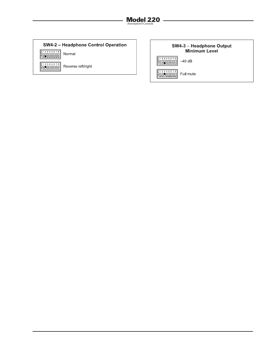
As you may have already guessed, when
selecting the reverse left/right mode of op-
eration everything is reversed! To be more
specific, when selected for reverse mode,
and the level/level mode is also selected,
the left control adjusts the headphone
output’s right channel (output jack’s ring
lead) while the right control adjusts the
left channel. When selected to the reverse
mode, and the level/balance is also se-
lected, turning the balance control in the
counterclockwise direction increases the
perceived level of the right channel, and
vice versa.
The reverse mode is provided specifically
for cases where a headset’s left and right
ear pieces are placed on a user’s head
in a reverse orientation. This ensures that
the user is provided with a consistent
and easy-to-use set of headphone level
controls.
Minimum Level Mode
Switch SW4-3 is used to configure the
headphone output’s minimum level. In the
–40 dB mode the minimum headphone
output level is 40 dB below maximum. The
headphone output channels will never fully
mute. This ensures that any audio signal
present on the selected Model 220 inputs
will always be present on the headphone
output. In most on-air broadcast applica-
tions this is the appropriate setting.
When the full mute mode is selected and
the level/level mode is also selected, mov-
ing either control to its fully counterclock-
wise position will cause its associated
channel to fully mute.
When the full mute mode is selected and
the level/balance mode is also selected,
turning the level control to its fully coun-
terclockwise position will cause both
headphone channels to mute. Turning the
balance control to either its fully clock-
wise or fully counterclockwise position will
cause the appropriate channel to mute.
Selecting the full mute mode may be
appropriate for applications where mini-
mizing the chance of audio “leakage”
is important. This could occur when the
connected headset or headphones are
at times placed on a desk or tabletop.
Main Output Source
Switch SW4-4 is used to select which
audio source is routed to the main output.
The choices are the output of the micro-
phone preamplifier or the output of the
compressor circuit. For most on-air ap-
plications the output of the microphone
preamplifier is the desired source. This
will provide the most natural audio quality
with the potential for a large amount
of dynamic range.
Figure 15. Headphone output minimum level
settings
Figure 14. Headphone control operation
settings