Headphone output operating modes – Studio Technologies 220 2013 User Manual
Page 22
Issue 5, February 2013
Model 220 User Guide
Page 22
Studio Technologies, Inc.
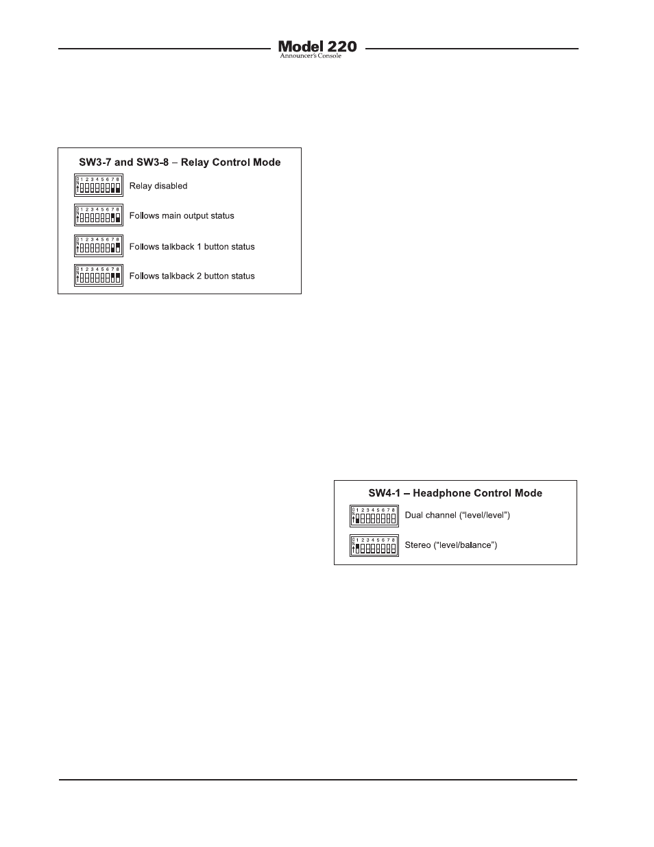
Auxiliary Relay Control Mode
Switch SW3-7 and SW3-8 configure the
operating mode of the auxiliary relay.
the way the controls function. With just
these three switches a wide range of oper-
ating modes can be configured. Carefully
reviewing the capabilities of the available
functions may prove worthwhile.
Dual-Channel or Stereo Mode
Switch SW4-1 is used to select whether
the controls provide a dual-channel
(“level/level”) or stereo (“level/balance”)
mode of operation. In the level/level mode
the two controls operate independently,
each controlling the level of one of the
headphone output channels. This mode
is generally used for on-air broadcast
applications where independent cue
signals are provided to the left- and right-
headphone channels. In the level/balance
mode the left rotary control sets the overall
output level for both headphone channels.
The right rotary control is used to adjust
the balance (the relative levels) of the left
and right channels. This mode is generally
best suited for applications where a stereo
cue source is being provided.
Reverse Left/Right Mode
Switch SW4-2 is used to select whether the
rotary controls are in the normal or reverse
left/right mode of operation. When selected
to the normal mode, and level/level mode
is also selected, the left control adjusts the
level of headphone output’s left channel.
(This is the signal that appears on the tip
lead of the ¼-inch 3-conductor jack.) The
right control adjusts the level of the right
channel. When selected to the normal
Figure 13. Headphone control mode settings
Figure 12. Auxiliary relay control mode settings
Four modes are available:
• Relay disabled: In this mode the relay is
disabled and will never change state.
• Follows main output status: In this mode
the relay will follow the status of the
main output. Specifically, the relay will
change state (energize) whenever the
main output is active.
• Follows talkback output 1 button sta-
tus: In this mode the relay will follow
the status of the button associated with
talkback output 1. Specifically, the relay
will change state (energize) whenever
the button is active.
• Follows talkback output 2 button sta-
tus: In this mode the relay will follow
the status of the button associated with
talkback output 2. Specifically, the relay
will change (energize) state whenever
the button is active.
Headphone Output Operating
Modes
The user is provided with two rotary level
controls (“pots”) that are associated with
the headphone output. Switches SW4-1,
SW4-2, and SW4-3 are used to configure