Operation, Conclusion – Studio Technologies 210 2008 User Manual
Page 21
Model 210 User Guide
Issue 4, October 2008
Studio Technologies, Inc.
Page 21
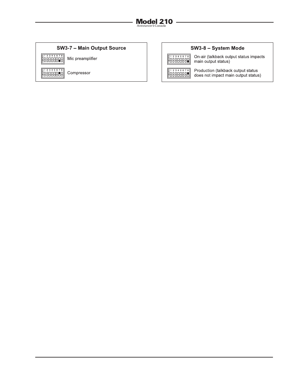
applications the output of the microphone
preamplifier is the desired source. This
will provide the most natural audio qual-
ity with the potential for a large amount of
dynamic range.
In some applications it may be desirable
for the output of the compressor circuit to
be routed to the main output. Appropriate
applications could include on-air broad-
cast situations where nonprofessional
talent is present. Controlling the dynamic
range of the audio signals on the main
output can limit the chance of cable cross-
talk and equipment overload. Another typi-
cal application where using the output of
the compressor would be when the Model
210’s system mode is selected for produc-
tion. In this case the main output would be
used as an additional talkback output and
dynamic range control could be beneficial.
System Mode
Switch SW3-8 is used to configure the
overall operating mode of the Model 210.
Specifically, it determines how the main
output operates vis-à-vis the talkback out-
put. Understanding how the two modes
impact overall system operation will en-
sure that correct operation and maximum
usability will occur. When selected to the
on-air mode, the main output will mute
whenever the talkback output is active.
The LED indicators associated with the
main output will light accordingly. The on-
air mode should be selected for all on-air
broadcast applications. It’s imperative that
the main output be muted whenever on-air
talent uses the talkback output to commu-
nicate with production personnel.
When the system mode is set for produc-
tion, the main output is never muted in
response to the talkback output being
active. This mode allows the main output
to be used, for example, as an additional
talkback output. In this way the main and
talkback outputs can be used indepen-
dently, with neither impacting the other.
This also allows both buttons to be used
simultaneously. When selected for the cor-
rect application, the production mode can
prove to be very useful. But it’s not appro-
priate for on-air use!
Conclusion
Once the switches have been set to the
desired configuration, the security plate
should be reattached. The four rubber
bumpers should be hand-tightened only.
No tools should be used.
Operation
At this point the desired input, output,
and power connections should have been
made. The button labels may have been
revised. Finally, the configuration switches
should have been set. Normal operation
of the Model 210 can now begin. The
unit will begin functioning as soon as a
power source is connected. As previ-
ously discussed, the power source can be
Figure 14. System mode settings
Figure 13. Main output source settings