Studio Technologies 210 2008 User Manual
Page 20
Issue 4, October 2008
Model 210 User Guide
Page 20
Studio Technologies, Inc.
3-conductor jack.) The right control ad-
justs the level of the right channel. When
selected to the normal mode, and the lev-
el/balance mode is also selected, turning
the balance control in the counterclock-
wise direction increases the perceived
level of the left channel, and vice versa.
As you may have already guessed, when
selecting the reverse left/right mode of op-
eration everything is reversed! To be more
specific, when selected for reverse mode,
and the level/level mode is also selected,
the left control adjusts the headphone
output’s right channel (output jack’s ring
lead) while the right control adjusts the
left channel. When selected to the reverse
mode, and the level/balance is also se-
lected, turning the balance control in the
counterclockwise direction increases the
perceived level of the right channel, and
vice versa.
The reverse mode is provided specifically
for cases where a headset’s left and right
ear pieces are placed on a user’s head in
a reverse orientation. This ensures that
the user is provided with a consistent
and easy-to-use set of headphone level
controls.
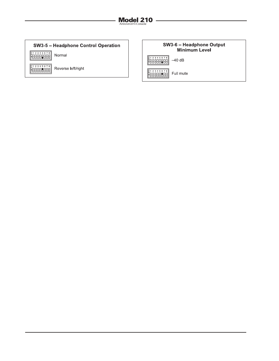
Minimum Level Mode
Switch SW3-6 is used to configure the
headphone output’s minimum level. In
the –40 dB mode the minimum head-
phone output level is 40 dB below
maximum. The headphone output chan-
nels will never fully mute. This ensures that
any audio signal present on the selected
Model 210 inputs will always be present
on the headphone output. In most on-air
broadcast applications this is the appropri-
ate setting.
When the full mute mode is selected,
and the level/level mode is also selected,
moving either control to its fully counter-
clockwise position will cause its associ-
ated channel to fully mute.
When the full mute mode is selected, and
the level/balance mode is also selected,
turning the level control to its fully coun-
terclockwise position will cause both
headphone channels to mute. Turning the
balance control to either its fully clock-
wise or fully counterclockwise position will
cause the appropriate channel to mute.
Selecting the full mute mode may be
appropriate for applications where mini-
mizing the chance of audio “leakage”
is important. This could occur when the
connected headset or headphones are at
times placed on a desk or tabletop.
Main Output Source
Switch SW3-7 is used to select which
audio source is routed to the main output.
The choices are the output of the micro-
phone preamplifier or the output of the
compressor circuit. For most on-air
Figure 12. Headphone output minimum level
settings
Figure 11. Headphone control operation
settings