Headphone output mode – Studio Technologies 210 2008 User Manual
Page 17
Model 210 User Guide
Issue 4, October 2008
Studio Technologies, Inc.
Page 17
This would allow both IFB channel 2 and
“spotter” audio to be heard in the head-
phone’s right-channel output. To achieve
this would require that switches SW2-1,
SW2-6, and SW2-7 be placed in their on
positions. Note that using another Model
210 at the “spotter” location could also
prove effective. It would provide all the
necessary microphone preamplifier, talk-
back routing, and headphone monitoring
resources.
Note that in some cases a user may
wish to wear a headset or a pair of head-
phones in a left/right orientation opposite
of what’s usual. In this situation the trans-
ducer designated for the left ear would
actually supply audio to the user’s right
ear, and vice versa. A specific application
when this occurs is where on-air talent
needs to have a headset’s boom micro-
phone come across the right side of their
face, rather than the more-typical left side.
In this case it’s important to select the
left- and right-channel headphone source
assignment accordingly. With the Model
210’s flexible source selection there’s no
reason why users, such as on-air talent,
shouldn’t have their cue sources assigned
correctly.
There may be cases where a monaural
“single-muff” headset or headphone will
be connected to the Model 210’s head-
phone output. In this case the desired
source(s) should be routed only to the left
channel. No sources should be assigned
to the right channel. This will eliminate the
short-circuit current that could occur when
a 2-conductor (monaural) plug is mated
with the Model 210’s 3-conductor (stereo)
headphone output jack.
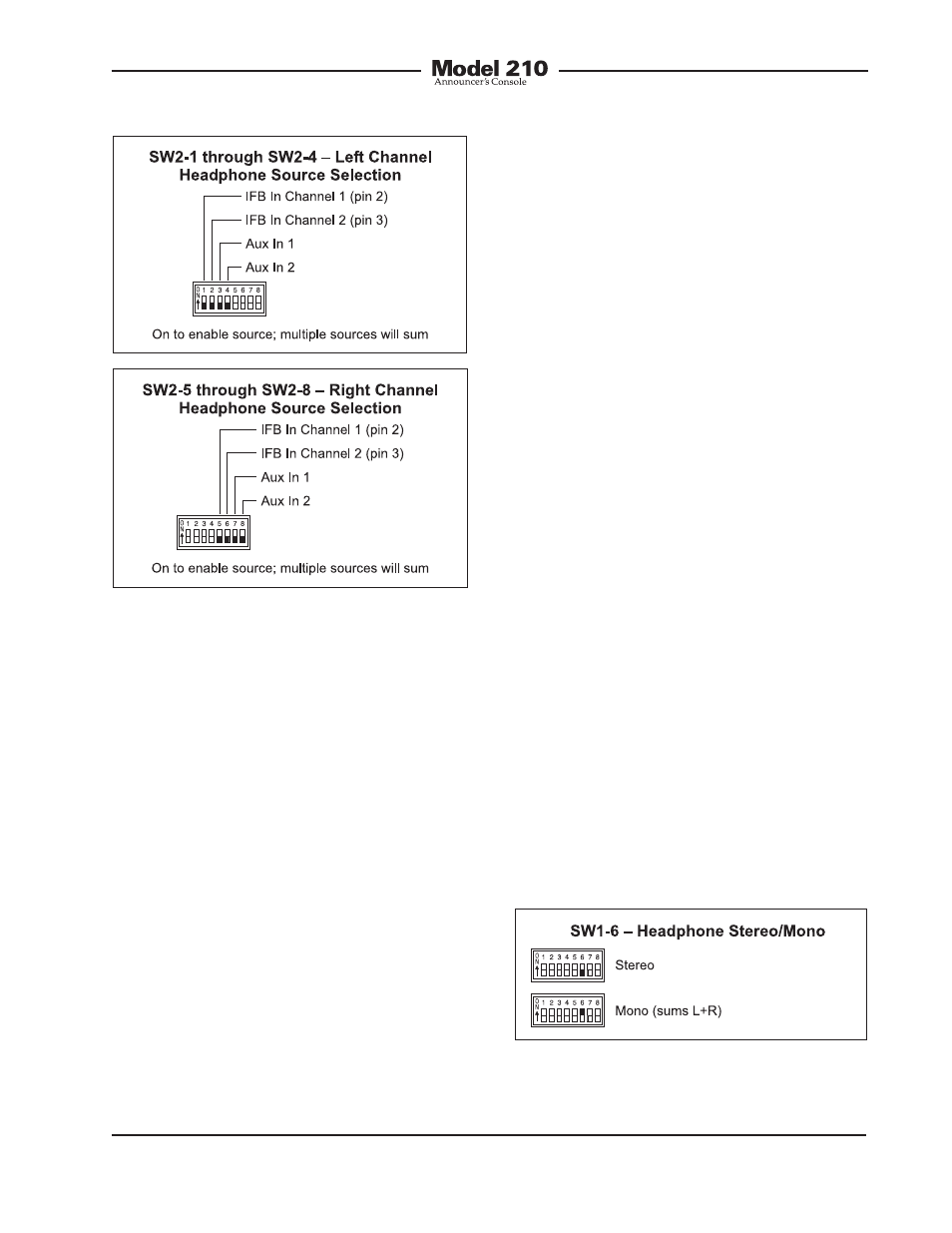
Headphone Output Mode
Switch SW1-6 allows a monaural head-
phone output to be created. This is
accomplished by summing (adding) the
selected left- and right-channel cue sig-
nals. The combined signals are sent to
both the left- and right-channel headphone
output driver circuits. The outputs of these
circuits connect, by way of 51 ohm series
protection resistors, to the headphone
output jack.
Figure 6. Left and right channel headphone
source selection settings
Figure 7. Headphone output mode settings