Technical notes, Factory test, Software version display – Studio Technologies 46A User Manual
Page 25
Model 46A User Guide
Issue 1, September 2014
Studio Technologies, Inc.
Page 25
Factory Test
Back-panel DIP switch 4 allows a factory
test mode to be enabled. During normal
operation DIP switch 4 should remain in
its off (down) position. When DIP switch
4 is in its on (up) position factory mode is
active. Enabling this mode will result in the
following operating condition: during an
auto null sequence the associated 4-wire
output channel will remain active. This will
allow the tones associated with the nulling
process to be present on the 4-wire out-
put. While not appropriate during actual
Model 46A use, it is interesting to “hear”
the nulling process take place. But unless
directed by factory personnel DIP switch 4
should remain in its off (down) position.
Technical Notes
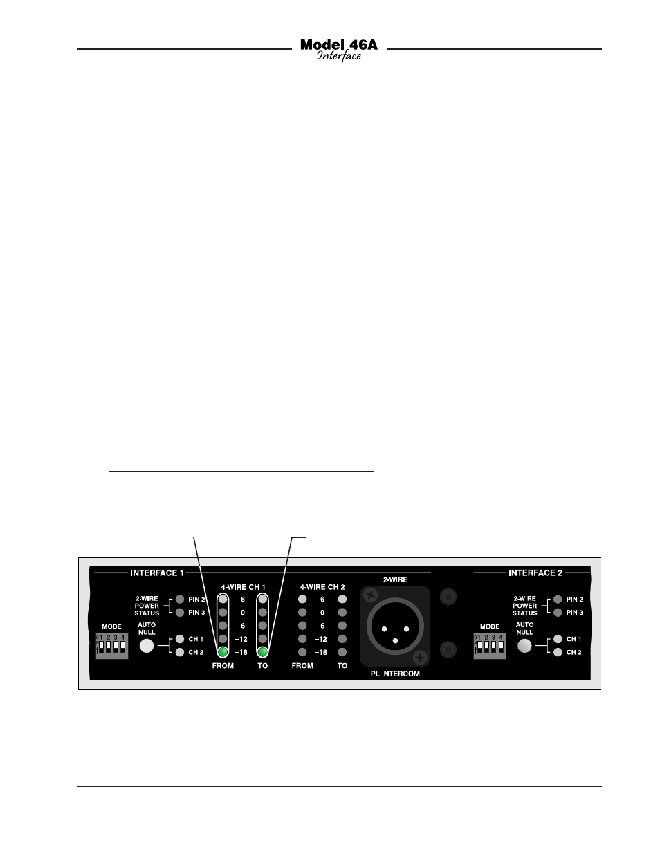
Software Version Display
A special Model 46A power-up sequence
allows the unit’s software version number
to be displayed. This is useful when work-
ing with factory personnel on application
support and troubleshooting situations.
The five meter LEDs associated with
FROM 4-wire channel 1 of interface 1 are
used to display the major release number
with a range of 1 through 5. The five meter
LEDs associated with TO 4-wire channel
1 of interface 1 are used to display the
release sub-number which again ranges
from 1 through 5. Refer to Figure 11 for
a detailed view of the meter LEDs and
the corresponding software version num-
bering scheme. The Model 46A’s initial
software release is version 1.1 which is
represented by the –18 LEDs of each
meter column being lit.
Figure 11. Detail of front panel showing the status LEDs that display the software version. In this
example, the software version is 1.1.
Major Release Number
Release Sub-Number
O
4
.4
O
O
3
.3
O
O
2
.2
O
1
.1