Auto null – Studio Technologies 46A User Manual
Page 23
Model 46A User Guide
Issue 1, September 2014
Studio Technologies, Inc.
Page 23
As a diagnostic aid the 2-wire power status
LED associated with pin 3 remains active in
the internal power mode. Whenever DC in
excess of approximately 18 volts is present
on pin 3 the LED will light. This condition
will normally never exist but could prove
useful in special circumstances.
Auto Null
Each of the Model 46A’s 2-channel inter-
faces has circuitry to automatically null the
two 2-wire-to-4-wire interfaces. Normally
this process is performed at the time of ini-
tial Model 46A configuration but there’s no
reason why “auto nulling” can’t be initiated
anytime one desires. The only time that
auto null must be performed is if conditions
have changed vis-à-vis the intercom user
devices and wiring connected to a Model
46A 2-wire PL interface connector. Even a
slight change to an intercom circuit, such
as adding or removing a section of cable,
is sufficient to require that the auto null
process be performed.
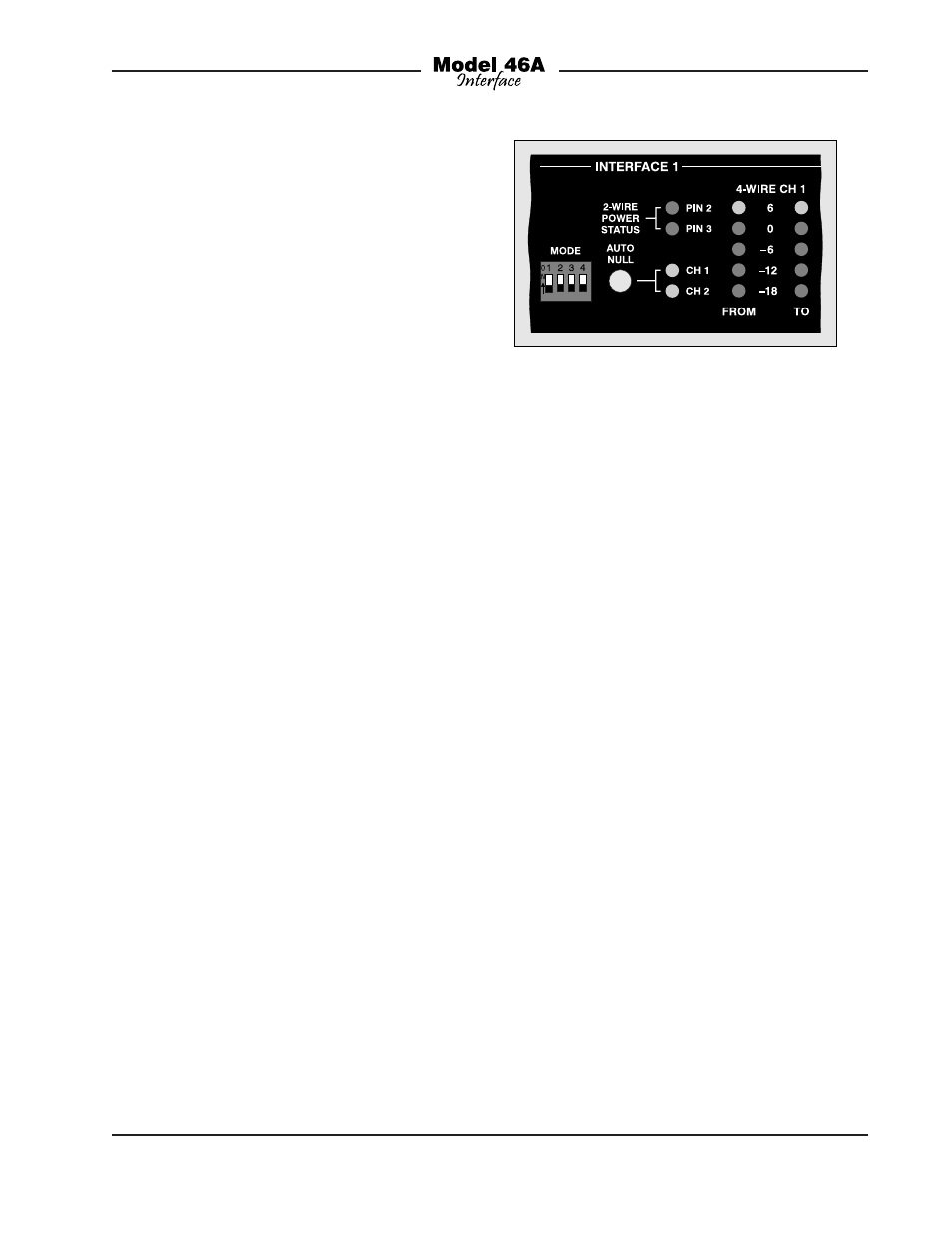
Two buttons, one associated with each
interface, are provided to activate the
auto null process. Refer to Figure 10 for a
detailed view. To initiate auto null simply
requires tapping a button. The process
begins by nulling channel 1 of an interface
and, when completed, moves on to chan-
nel 2. Two LEDs provide a visual indication
of the auto null process, flashing when the
auto null process for its respective channel
is active.
An actual auto null sequence starts by
muting the 4-wire input and output signal
paths associated with the specific channel
to be nulled. Then a short period of 24 kHz
signal is sent out the 2-wire PL intercom
interface channel. This will turn off micro-
phones on those connected user devices
that are compatible with the RTS TW-Series
“mic kill” protocol. The actual auto nulling
process will next be performed. A series of
tones will be sent out the 2-wire interface.
Other Model 46A circuitry, under software
control, will rapidly perform adjustments to
achieve the best null possible. After the ad-
justments are made the results are stored
in non-volatile memory. Once the process
has completed the 4-wire input and output
paths are again activated.
Advanced configuration DIP switch 2, locat-
ed on the back panel, allows an indepen-
dent auto null button mode to be selected.
If DIP switch 2 is in its on (up) position, the
front-panel pushbuttons will function in
quite a different manner. In the independent
mode, a single tap of a button will cause
channel 1 to auto null. Two taps will cause
channel 2 to auto null. By observing the
operation of the two auto null status LEDs
it will become readily apparent which of the
button modes has been selected.
If possible, prior to performing an auto null
it’s polite to warn all personnel who are
actively using the connected intercom de-
vices. The tones sent to the 2-wire intercom
circuit during the nulling process are not
excessively loud or obnoxious, but most
users might want to remove their headsets
Figure 10. Detail of front panel showing auto
null section