Remote control inputs – Studio Technologies 46A User Manual
Page 13
Model 46A User Guide
Issue 1, September 2014
Studio Technologies, Inc.
Page 13
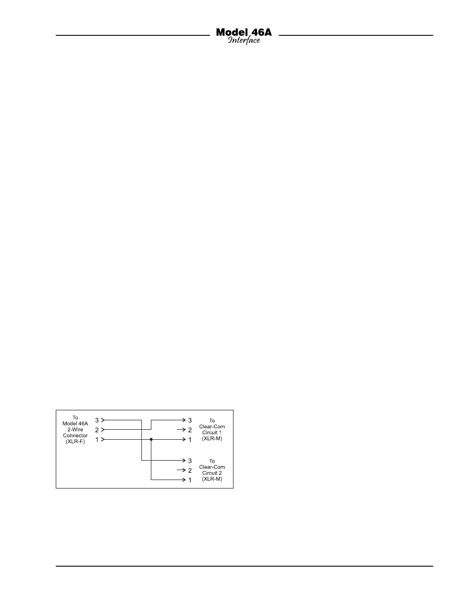
be prepared. These adapters will “split” the
Model 46A’s 2-wire PL intercom connectors
into two 3-pin male XLR connectors, one
for each audio channel. Pin 1 of the female
3-pin XLR intended to mate with the Model
46A will connect to pin 1 of both 3-pin male
XLR connectors. Pin 2 of the female XLR
will go to pin 3 of the male XLR designated
as channel 1. Pin 3 of the female XLR will
go to pin 3 of the male XLR designated as
channel 2. Refer to Figure 2 for details. Us-
ing two adapter cables the Model 46A can
be directly interconnected with four Clear-
Com intercom circuits. However, power for
the connected devices must be provided
by external power sources. The Model
46A’s ability to supply intercom power will
not be utilized.
Note: It’s critical that the correct configu-
ration settings be made when using the
Model 46A’s interfaces to support four
independent intercom circuits. Specifically,
the 2-wire power source configuration DIP
switches must be set for external. In addi-
tion, the auto terminate disable DIP switch
must be placed in its on (up) position.
Refer to the Configuration and Advanced
Configuration sections of this user guide
for details.
Remote Control Inputs
The Model 46A allows connection of three
externally provided DC signals. These
signals can provide remote control opera-
tion of three functions: auto nulling for
interface 1, auto nulling for interface 2, and
a special “mic kill” function. Remote con-
trol of the auto nulling functions provides a
resource identical to that of the front-panel
pushbutton switches. The exact manner in
which the buttons and the remote control
inputs operate depends on the setting of
auto null button mode configuration DIP
switch. The “mic kill” function is unique,
only being available using the remote
control input. It causes a 500 millisecond
“burst” of 24 kHz signal to be sent se-
quentially to both of the 2-wire partly-line
interface channels associated with each
of the Model 46A’s two interfaces. To
clarify, a “mic kill” signal is sent to a total
of four intercom channels whenever the
function is activated. Independent control
of sending “mic kill” signals to interface 1
or interface 2 is not supported. User inter-
com devices compatible with this 24 kHz
“mic kill” signal include RTS TW-Series
beltpacks such as the BP325.
The opto-coupled remote control inputs
are designed for direct connection with
3.3 and 5 volt DC logic signals. An internal
475 ohm resistor, in series with each opto-
coupler’s photodiode, acts to limit the
current flow. Signals of up to 32 volts DC
can be safely connected as long as the
current is limited to 20 mA maximum. If
necessary, an external resistor can serve
to limit the current. For example, with a 12
volt DC signal using a 560 ohm, ¼-watt re-
sistor in series with the connection would
be appropriate. With a 24 volt DC control
signal a series resistor of 1.8 k (1800) ohm
Figure 2. Adapter cable wiring diagram