Auto null button – Studio Technologies 46A User Manual
Page 18
Issue 1, September 2014
Model 46A User Guide
Page 18
Studio Technologies, Inc.
applications in which the three conductors
of a cable support both DC power and two
channels of audio. It’s also compatible in
situations where all three conductors of a
Clear-Com single-channel intercom circuit
are connected to the Model 46A. In this lat-
ter case only one of the Model 46A’s audio
channels will be used.
There may be situations where it’s neces-
sary for the two channels associated with
each Model 46A interface be used with
separate 2-wire party-line circuits. An ex-
ample of this might be where two “loops”
of single-channel beltpacks, such as units
from Clear-Com, need to be connected.
Adapter cables as shown in Figure 2 would
be used. In this case the intercom circuit’s
DC power will not be connected to the
Model 46A, but only to the user devices. In
this scenario, a DC voltage won’t be pres-
ent on pin 2 or pin 3. Another example of
this might be where adapter boxes with DC
blocking are used to interconnect intercom
circuits with the Model 46A. In both these
cases a DC voltage won’t be present on
either pin 2 or 3 and the Model 46A will au-
tomatically apply 200 ohm terminations. In
both these cases the termination will be in
error and will result in incorrect audio levels
due a “double-termination” condition.
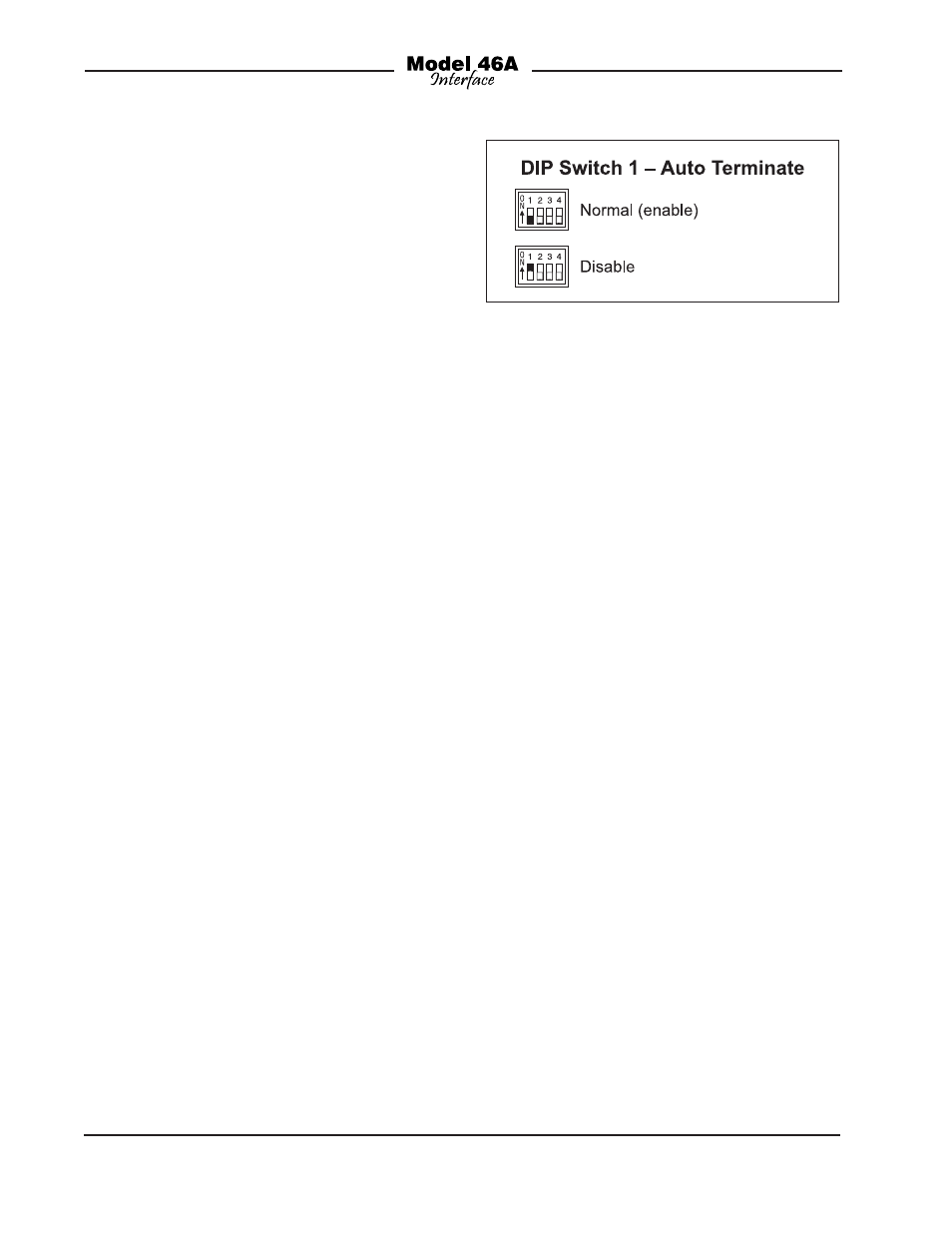
To prevent this problem the auto terminate
function can be disabled. Referring to Fig-
ure 7, when DIP switch 1 is in its off (down)
position the auto terminate function is ac-
tive. When switch 1 is in its on (up) posi-
tion the auto terminate function associated
with each interface is disabled. Repeating
for clarity, the auto terminate function ap-
plies to both interfaces 1 and 2. With the
auto terminate function disabled the two
interfaces, when set for external power, will
operate normally with the exception that
pins 2 and 3 will never be terminated by
the Model 46A’s circuitry.
The auto terminate function should be
disabled only when absolutely necessary;
it’s possible that a significant downside
could be experienced. With auto terminate
disabled it’s important that properly ter-
minated 2-wire party line-intercom circuits
be connected to pins 2 or 3 on the Model
46A’s 2-wire PL connectors. If they are not
connected, it’s likely that audio oscilla-
tions, noise, and distortion will be gener-
ated in the Model 46A’s 2-wire-to-4-wire
converter circuitry. These audio artifacts
will not cause any damage, but will be
sent out the 4-wire line output connectors.
Users of the 4-wire equipment may be less
than pleased with what they hear!
Auto Null Button
One pushbutton switch is associated with
each of the Model 46A’s two interface
circuits. An advanced configuration pa-
rameter allows selection of the button’s
operation. The choices are dual auto null
mode and independent auto null mode.
When dual auto null mode is selected a
single tap of one of the two front-panel
pushbutton switches initiates a routine
that begins with channel 1’s auto null se-
quence taking place followed immediately
by channel 2’s auto null sequence being
performed. Note that the mode selected
Figure 7. DIP Switch 1—Auto Terminate