Factory test – Studio Technologies 46A User Manual
Page 19
Model 46A User Guide
Issue 1, September 2014
Studio Technologies, Inc.
Page 19
for auto null button operation will also
apply to the remote auto null inputs.
The independent auto null mode allows
the auto null function to be initiated for
each channel as desired. A single tap will
start the auto null routine for channel 1.
Two taps will start the routine for channel 2.
When DIP switch 2 is in its off (down) posi-
tion the dual auto null mode is selected.
This is provided specifically for cases where
the Model 46A’s 2-wire party line interfaces
will be used with dual channel intercom
user devices. As an example: the RTS TW-
Series provides two independent audio
channels, as well as power, over a single
3-conductor cable. In a case such as this
it’s useful for both of the hybrid circuits
associated with an interface to be auto
nulled at approximately the same time.
The dual auto null mode allows a single
tap of the button to initiate nulling of both
hybrid circuits.
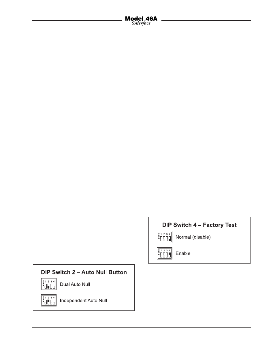
Referring to Figure 8, when DIP switch 2
is in its on (up) position the independent
auto null mode is selected. This would
be appropriate for applications in which
the two audio paths associated with each
interface are used with independent party-
line intercom circuits. This situation might
arise when two Clear-Com single-channel
intercom circuits are connected to one of
the Model 46A’s 2-channel interfaces. The
hybrid circuit associated with each chan-
nel can be auto nulled as desired. Another
example would be in an RTS TW-Series
application that uses source assignment
panels. The “SAP” panels would be used
to route multiple intercom channels to vari-
ous sets of user devices as desired. In this
case, the two channels associated with
each Model 46A interface will often end up
not routed to the same user device; inde-
pendent auto nulling is certainly desired.
Factory Test
Back-panel DIP switch 4 is used to select
between normal mode and factory test
mode. Referring to Figure 9, when DIP
switch 4 is in its off (down) position the
Model 46A operates in its standard fash-
ion. When DIP switch 4 is in its on (up)
position the factory test mode is selected.
As expected, when the Model 46A is
deployed in the field DIP switch 4 should
remain in its off (down) position. No dam-
age to the Model 46A or connected equip-
ment will occur when factory test mode is
active.
Figure 8. DIP Switch 2—Auto Null Button
Figure 9. DIP Switch 4—Factory Test