Connecting the switch pro – Smithco Switch Pro Installation & Operation Manual User Manual
Page 13
Manual No. 016-0171-219
9
Installation
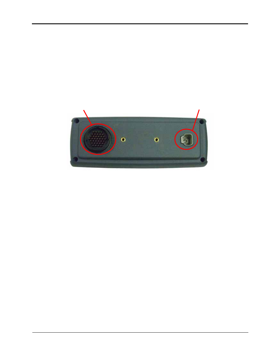
Connecting the Switch Pro
Note:
For kits including a combo cable (P/N 115-0171-820 or 821), refer to Appendix A, Switch Pro
Combo Cable, for installation instructions.
Refer to Appendix B, System Diagrams, for detailed system connection diagrams. These drawings may be
helpful for understanding the Switch Pro system and connections.
1.
Refer to the Envizio Pro or Viper Pro Installation & Operation Manual when installing the Envizio Pro or
Viper Pro interface cables (P/N 115-0171-745 or 746). These cables are included in the core Envizio Pro or
Viper Pro systems and detailed installation procedures are detailed in the installation section for the Envizio
Pro or Viper Pro field computer.
2.
Once the Envizio Pro/Viper Pro interface cables are installed, connect the auxiliary power output connector
to the back of the Switch Pro.
3.
Connect the Switch Pro to the existing SCS console cable.
a.
For Switch Pro systems replacing SCS 4400 consoles, connect the existing console cable directly to
the cable port on the back of the Switch Pro switch box.
b.
Switch Pro systems replacing SCS 440/450 consoles require the the Switch Pro console cable (P/N
115-0171-803) to connect with the existing SCS 440/450 console cable. Connect the large round
connector to the back of the Switch Pro. The existing SCS 440/450 console cable will connect to the
smaller male connector on the Switch Pro console cable (P/N 115-0171-803).
Switch Pro Cable Port
Logic Power Port