Timing diagram, Reading latched encoder counts, Encoder connections – Sensoray 421 User Manual
Page 9: Power connections, Clock connections
Sensoray Model 421 Instruction Manual
Page 7
A
B
1
2
3
4
5
6
7
8
Valid count transitions vs. counter operating mode
Counter Configuration
Valid Count
Transitions
Mode
Function
Up
Down
0
Quadrature x2
6, 8
1, 3
1
Quadrature x4
5, 6, 7, 8
1, 2, 3, 4
2
Quadrature x1
8
1
3
Single Phase x1
---
1
4
Quadrature x2
1, 3
6, 8
5
Quadrature x4
1, 2, 3, 4
5, 6, 7, 8
6
Quadrature x1
1
8
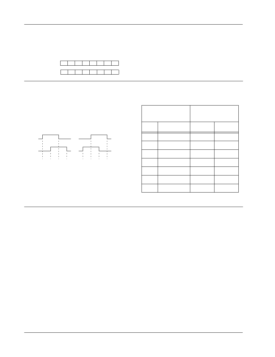
Timing Diagram
Encoder counters change state (count up or down)
upon detection of any valid input transition. All
possible transitions are shown in the timing diagram
below. For example, transition number 1 specifies a
rising edge on the “A” phase while “B” is held low.
Valid transitions depend on the operating mode. The
table to the right lists valid transitions for each mode.
In mode 0, for example, a counter will count up only
at transitions 6 and 8, and will count down only at
transitions 1 and 3.
Reading Latched Encoder Counts
After executing a Latch command, the latched data
may be read from ports CNTLSB and CNTMSB.
CNTLSB (14):
CNTMSB (15):
d
7
d
6
d
5
d
4
d
3
d
2
d
1
d
0
d
15
d
14
d
13
d
12
d
11
d
10
d
9
d
8
Port CNTLSB contains the least-significant byte of
the encoder counts and port CNTMSB contains the
most-significant byte.
It makes no difference which byte is read first. The
data value remains latched until the next Latch
command.
Encoder Connections
Connector P3 is used to make all electrical
connections to external encoders. Each counter
channel is allocated six pins on connector P3: +5V,
GND, +A, -A, +B and -B.
Power Connections
The +5V and GND pins may optionally be used to
power an external encoder. If an external encoder
power source is used, you must connect GND to the
external power supply return. Failure to connect
these returns may damage the 421 board.
Clock Connections
Each counter channel is assigned four pins on
connector P3 for connection to the phase inputs.
Each phase makes two electrical connections to P3 in
the form of a differential RS422 pair. The A phase
inputs consist of +A and -A, while the B inputs
consist of +B and -B. Connections to these four
inputs depend on the type of device to be interfaced.
For a variety of reasons, RS422 termination resistors
are not supplied on the 421 board. If your encoder (or
other pulse source) employs RS422 drivers, you may
need to supply external termination resistors near
connector P3 for proper operation. Refer to your
encoder manufacturer’s documentation for
recommended RS422 termination circuitry and
practice.