Circuit board testing, Nm1250r, Electronic control tester – Scotsman NM1250R User Manual
Page 38
INSTRUCTIONS FOR USING TESTER MODEL FC1
(Optional, order part no. A33942-001)
(These instructions assume that the unit will not run, and prior investigation of electric power,
controls, and mechanical parts indicates that the electronic circuit may be at fault.)
/////////////////////////////////////////////////////////////////////////////WARNING/////////////////////////////////////////////////////////////
These procedures require the machine to be connected to the power supply. The voltages of the
electronic circuit are very low, but HIGHER VOLTAGES ARE PRESENT IN THE UNIT. Do not
touch anything but the tester while the unit is being checked out. Make all connections to the
circuit board with the ELECTRICAL POWER OFF.
////////////////////////////////////////////////////////////////////////////////////////////////////////////////////////////////////////////////////////////
Bin Control
Note: All testing is done with the
electrical power on, the master switch on, and
all reset switches "reset" .
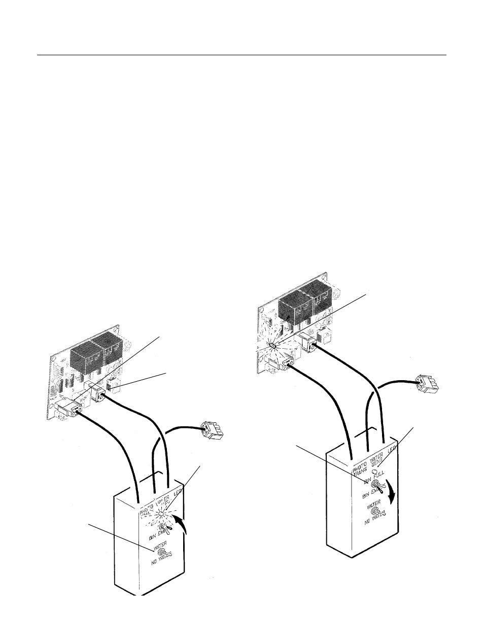
1. Unplug "photo trans" and "LED" connectors
from the circuit board.
2. Plug "photo trans" and "LED" connectors
from the tester into the circuit board.
a. Move the "bin full" switch on the tester to
Full. The light on the tester should be ON.
If the light on the tester is not on, the circuit
board should be replaced.
b. If the light on the tester IS on, move the
"bin full" switch to Bin Empty. The light on the
tester should go OFF, and the Bin Empty light
on the circuit board should go ON.
If the machine still does not run, replace the
ice level sensors.
ELECTRONIC CONTROL TESTER
PHOTO TRANS
LED
LIGHT
GOES ON
SWITCH TO
"FULL"
LIGHT GOES ON
SWITCH TO
"BIN EMPTY"
LIGHT
GOES OFF
NM1250R
November, 1988
Page 38