Scotsman NDE554 User Manual
Introduction
INTRODUCTION
To the owner or user: The service manual you are
reading is intended to provide you, and the
maintenance or service technician with the
information needed to install, start up, clean,
maintain, and service this ice maker-dispenser.
This machine is a combination nugget ice maker
and countertop dispenser, with the option of wall
mounting.
The ice making section is equipped with the
following features: electronic controls for bin level
and low water; thermostatic expansion valve; front
service for most components; and R-404A (HP62)
refrigerant. The ice dispensing section is a
seamless plastic storage bin, with a stainless steel
rotating vane to sweep the ice into the dispensing
chute.
NDE554 & NDE654
March 2000
Page 1
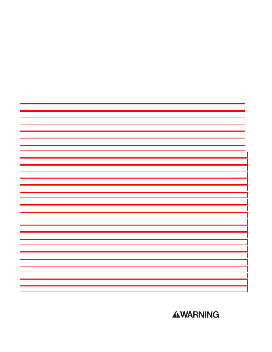
Table of Contents
FOR THE INSTALLER: Specifications · · · · · · · · · · · · · · · · · · · · · · · · · · · · · · Page 2
FOR THE INSTALLER: Environmental Limitations · · · · · · · · · · · · · · · · · · · · · · · · Page 3
FOR THE INSTALLER · · · · · · · · · · · · · · · · · · · · · · · · · · · · · · · · · · · · · · Page 4
FOR THE INSTALLER: Wall Mount Kit · · · · · · · · · · · · · · · · · · · · · · · · · · · · · · Page 5
FOR THE PLUMBER · · · · · · · · · · · · · · · · · · · · · · · · · · · · · · · · · · · · · · · Page 6
FOR THE ELECTRICIAN · · · · · · · · · · · · · · · · · · · · · · · · · · · · · · · · · · · · · Page 7
FOR THE INSTALLER: Final Check List · · · · · · · · · · · · · · · · · · · · · · · · · · · · · Page 8
COMPONENT DESCRIPTION · · · · · · · · · · · · · · · · · · · · · · · · · · · · · · · · · · Page 10
COMPONENT DESCRIPTION · · · · · · · · · · · · · · · · · · · · · · · · · · · · · · · · · · Page 11
COMPONENT DESCRIPTION: Control Box · · · · · · · · · · · · · · · · · · · · · · · · · · · Page 12
ELECTRICAL SEQUENCE · · · · · · · · · · · · · · · · · · · · · · · · · · · · · · · · · · · · Page 13
SENSOR MAINTENANCE · · · · · · · · · · · · · · · · · · · · · · · · · · · · · · · · · · · · Page 18
BEARING MAINTENANCE · · · · · · · · · · · · · · · · · · · · · · · · · · · · · · · · · · · · Page 19
AUGER MAINTENANCE · · · · · · · · · · · · · · · · · · · · · · · · · · · · · · · · · · · · · Page 20
CONTROL SYSTEM DIAGNOSTICS · · · · · · · · · · · · · · · · · · · · · · · · · · · · · · Page 23
REMOVAL AND REPLACEMENT · · · · · · · · · · · · · · · · · · · · · · · · · · · · · · · · Page 24
REMOVAL AND REPLACEMENT: Bearing And Breaker · · · · · · · · · · · · · · · · · · · · Page 25
REMOVAL AND REPLACEMENT · · · · · · · · · · · · · · · · · · · · · · · · · · · · · · · · Page 26
REMOVAL AND REPLACEMENT: Water Seal · · · · · · · · · · · · · · · · · · · · · · · · · · Page 27
REMOVAL AND REPLACEMENT · · · · · · · · · · · · · · · · · · · · · · · · · · · · · · · · Page 28
TO REMOVE AND REPAIR THE GEARMOTOR ASSEMBLY · · · · · · · · · · · · · · · · · · Page 29
REFRIGERATION SERVICE · · · · · · · · · · · · · · · · · · · · · · · · · · · · · · · · · · · Page 30
Note this symbol when it appears.
It marks a possible hazard.
Document Outline
- Table of Contents
- FOR THE INSTALLER: Specifications Page 2
- FOR THE INSTALLER: Environmental Limitations Page 3
- FOR THE INSTALLER Page 4
- FOR THE INSTALLER: Wall Mount Kit Page 5
- FOR THE PLUMBER Page 6
- FOR THE ELECTRICIAN Page 7
- FOR THE INSTALLER: Final Check List Page 8
- INITIAL START UP Page 9
- COMPONENT DESCRIPTION Page 10
- COMPONENT DESCRIPTION Page 11
- COMPONENT DESCRIPTION: Control Box Page 12
- ELECTRICAL SEQUENCE Page 13
- OPERATION: Water Page 14
- OPERATION: Refrigeration Page 15
- OPERATION: Ice Vending Page 16
- CLEANING and SANITIZING Page 17
- SENSOR MAINTENANCE Page 18
- BEARING MAINTENANCE Page 19
- AUGER MAINTENANCE Page 20
- SERVICE DIAGNOSIS: Page 21
- SERVICE DIAGNOSIS Page 22
- CONTROL SYSTEM DIAGNOSTICS Page 23
- REMOVAL AND REPLACEMENT Page 24
- REMOVAL AND REPLACEMENT: Bearing And Breaker Page 25
- REMOVAL AND REPLACEMENT Page 26
- REMOVAL AND REPLACEMENT: Water Seal Page 27
- REMOVAL AND REPLACEMENT Page 28
- TO REMOVE AND REPAIR THE GEARMOTOR ASSEMBLY Page 29
- REFRIGERATION SERVICE Page 30