Glass filler kit, Nd550, For the installer: water glass filler kit – Scotsman ND550 User Manual
Page 6
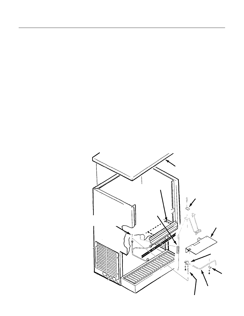
FOR THE INSTALLER: Water Glass Filler Kit
Installation Instructions for KWGF
///////////////////////////CAUTION////////////////////////////////
Shut off potable water supply to icemaker -
dispenser.
/////////////////////////////////////////////////////////////////////////
///////////////////////////WARNING////////////////////////////
Disconnect electrical power to icemaker -
dispenser.
//////////////////////////////////////////////////////////////////////////
1. Remove screws, and remove top panel
2. Remove screws, and remove both front panels.
3. Remove screws, and remove the filler
plate-scrap the plate.
4. Locate water solenoid valve assembly and two
red wires in the kit. Attach the (2) red wires to the
solenoid terminals.
5. Locate the water line assembly and the water
line adapter. Connect to water solenoid valve.
Fitting size will determine location.
6. Remove plug from potable water line.
7. Install valve plate and switch assembly to the
dispenser, replace the filler plate removed in step
3.
8. Attach the water solenoid
assembly to the underside of the
upper compartment using (2)
screws and lockwashers into the
threaded holes provided.
9. Attach the water line adapter
and solenoid valve assembly to
water line where plug was removed
in step 6.
10. Attach clamp and #8-32 x 3/4
phillips machine screw to secure
the water line assembly.
11. Insert glass filler lever through
the square slot in the valve plate
and switch assembly. Attach to
dispenser with (2) arm clamps and
(2) #6-32 x 1/2 machine screws.
12. Check and adjust the
microswitch so that the glass filler
lever pushes the micro-switch
button.
13. Attach the glass filler lever
spring to glass filler lever. The large
hook goes to the filler lever, the
small one to the hole in the
dispenser base directly below.
14. Attach the red wire connected to the solenoid
to the switch on the valve plate. Attach the blue
wire to the switch on the valve plate.
••
Route the free red wire from the solenoid,
attach to the terminal strip to the second
terminal from the left.
••
Route the blue wire from the switch to the
control box, attach the red wire to the terminal
strip and attach the blue wire to the leftmost
terminal.
15. Turn on water, check for leaks. Replace
panels, switch on power supply, check operation.
TOP PANEL
ARM CLAMPS
SWITCH
PLATE
ASSEMBLY
CLAMP
WATER
LINE
ADAPTER
PLUG
SPRING
FILLER
PLATE
VALVE
ND550
August, 1989
Page 6