Thermal consideration, Features descriptions (con.) – Delta Electronics Delphi NC30 User Manual
Page 10
DS_NC12S30A_05222008
10
THERMAL CONSIDERATION
Thermal management is an important part of the
system design. To ensure proper, reliable operation,
sufficient cooling of the power module is needed over
the entire temperature range of the module. Convection
cooling is usually the dominant mode of heat transfer.
Hence, the choice of equipment to characterize the
thermal performance of the power module is a wind
tunnel.
Thermal Testing Setup
Delta’s DC/DC power modules are characterized in
heated vertical wind tunnels that simulate the thermal
environments encountered in most electronics
equipment. This type of equipment commonly uses
vertically mounted circuit cards in cabinet racks in
which the power modules are mounted.
The following figure shows the wind tunnel
characterization setup. The power module is mounted
on a test PWB and is vertically positioned within the wind
tunnel.
Thermal Derating
Heat can be removed by increasing airflow over the
module. To enhance system reliability, the power
module should always be operated below the
maximum operating temperature. If the temperature
exceeds the maximum module temperature, reliability
of the unit may be affected.
The maximum acceptable temperature measured at
the thermal reference point is 125
℃.
This is shown in
Figure 36 & 41.
FEATURES DESCRIPTIONS (CON.)
Voltage Margining
Output voltage margining can be implemented in the
NC30/NC40 modules by connecting a resistor, R
margin-up
,
from the Trim pin to the ground pin for margining up the
output voltage. Also, the output voltage can be adjusted
lower by connecting a resistor, R
margin-down
, from the Trim
pin to the output pin. Figure 34 shows the circuit
configuration for output voltage margining adjustment.
Cout
Rmargin-down
0
Vt
-SENSE
Rmargin-up
+SENSE
GROUND
Rs
Vout
TRIM
Figure 34:
Circuit configuration for output voltage margining
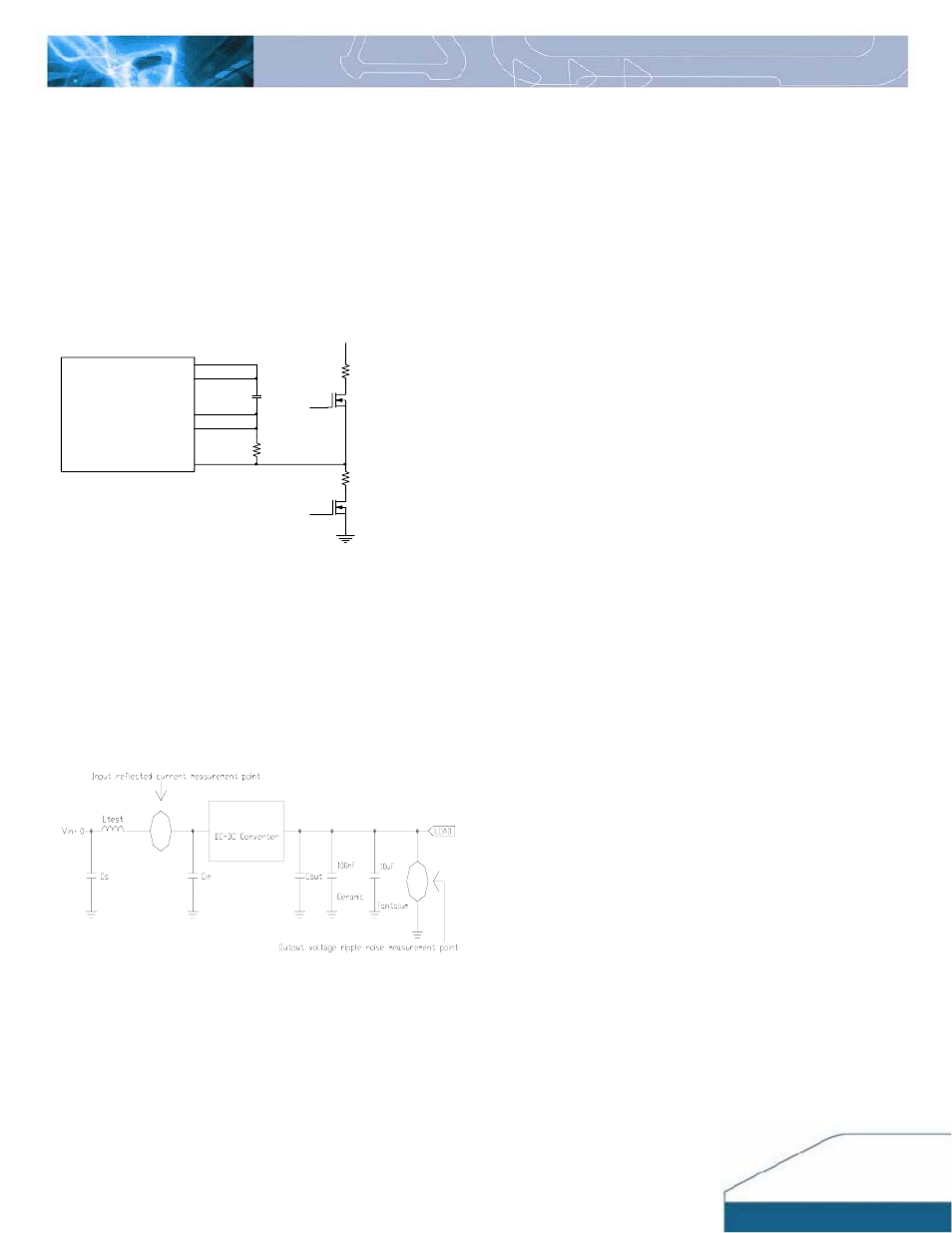
Reflected Ripple Current and Output Ripple and
Noise Measurement
The measurement set-up outlined in Figure 35 has been
used for both input reflected/ terminal ripple current and
output voltage ripple and noise measurements on NC
series converters.
Cs=270uF*1 Ltest=1.4uH Cin=270uF*1 Cout=680uF*2
Figure 35
:
Input reflected ripple/ capacitor ripple current and
output voltage ripple and noise measurement setup for NC30