Ct120/300/800/2400, Fms sensor wiring guide, Figure 5.1: fms wiring – RLE FMS User Manual
Page 5
SHEET:
5 OF 16
104 Racquette Drive
Fort Collins, CO 80524
(970) 484-6510 Phone
(970) 484-6650 Fax
www.rletech.com
FMS Sensor Wiring Guide
10061_FMS Rev 2.0 (8/13)
CT120/CT300/CT800/CT2400 FMS Integration
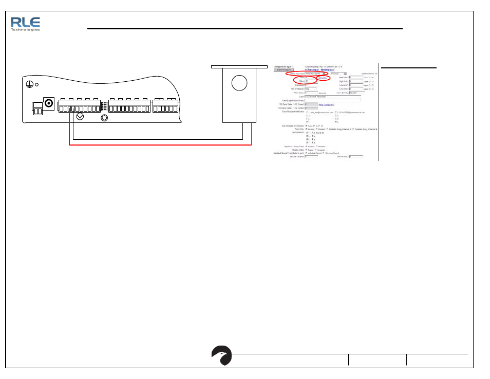
1. Set Input Type to an
Analog 4-20 mA Input.
2. For a 0-100 Amp setting, use
a gain of 25 and an offset of
-25.
3. For other settings, use the
integrated gain/offset
calculator.
FMS Configuration
Figure 5.1: FMS Wiring
Figure 5.2: FMS Input Configuration Interface
P1
V DC
TB 1
V DC
+ -
EXT ERNAL
24VDC
+ +
Ch1
+ -
Ch2
+ -
Ch3
+ -
Ch4
+ -
TB2 Input 1-4
Ch5
+ -
Ch6
+ -
Ch7
+ -
TB 3 Input 5-8
Ch8
+ -
EXT ERNAL
GND
- -
TB 4
NC NO C
RELAY 1
NC NO C
RELAY 2
+
-
1
2
3