Tab drive and media sensor assembly components, Clockwise = more tab area on bottom, Counter-clockwise = more tab area on top – Rena T-350 User Manual
Page 9
GETTING ACQUAINTED
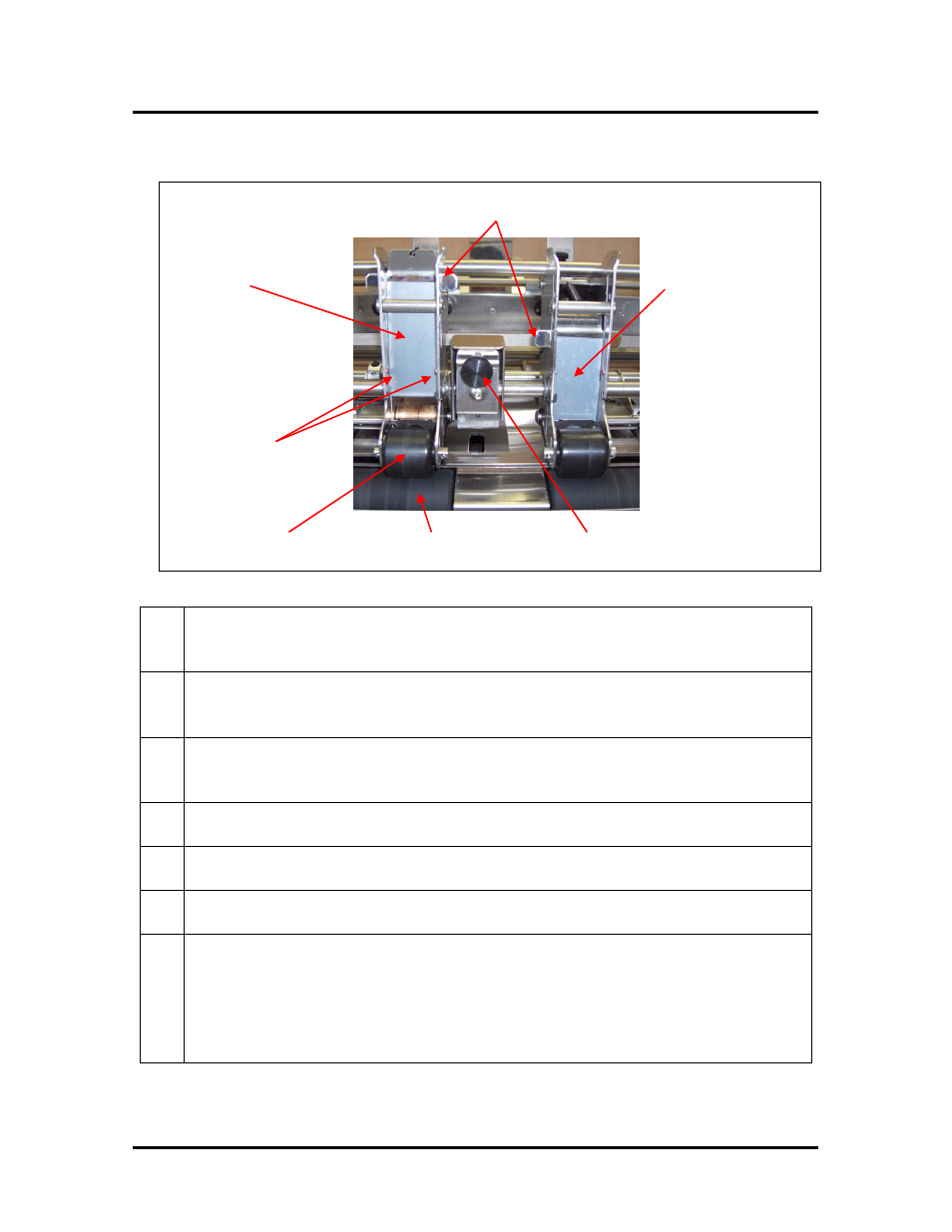
Tab Drive and Media Sensor Assembly Components
PEEL BAR LOCATOR
TAB FOLD ADJUSTMENT
KNOB
PEEL BAR
(down, run position)
PEEL BAR
(up, threading position)
UPPER PRESSURE
ROLLERS
LOCATOR DOTS (red)
LOWER EXIT
ROLLER
1.
PEEL BAR LOCATOR – Use to set the peel bar location to the threading (up)
or tabbing (down) position. Locators lock the peel bar into position. Pull forward
to release, then slide up or down.
2.
PEEL BAR (UP) – The upper position allows the tab web to be fed through the
opening at the bottom of the tab drive assembly, and out the back; just under the
tractor drive roller.
3.
PEEL BAR (DOWN) – When in the lower position, this device creates a sharp
bend in tab web. This sharp bend causes the tab to be released from the backing
as the tab web is driven around the bottom edge of this bar.
4.
LOCATOR DOTS (RED) – Alignment marks used to locate the correct starting
location for the tab on the web (backing).
5.
UPPER PRESSURE ROLLERS – Provides the pressure to seal the tab to the
top of the mail piece (media).
6.
LOWER EXIT ROLLER –Seal the tab to the bottom of the mail piece (media)
while driving the media out of the tabber.
7.
TAB FOLD ADJUSTMENT KNOB
– Adjusts the position/angle of the paper
sensor, which in-turn adjusts the fold position of the tab.
clockwise = more tab area on bottom
counter-clockwise = more tab area on top
Tip: Start with knob turned fully clockwise. Test and adjust from there.
Don’t over-tighten this knob.
T-350 Operations Rev. 3/23/2009
9