Electrical connection – REMKO DN 32 User Manual
Page 7
7
Electrical connection
All electrical installation work is to be
performed by specialty companies.
Disconnect the voltage supply when
connecting the electrical terminals.
Observe the VDE guidelines.
ATTENTION
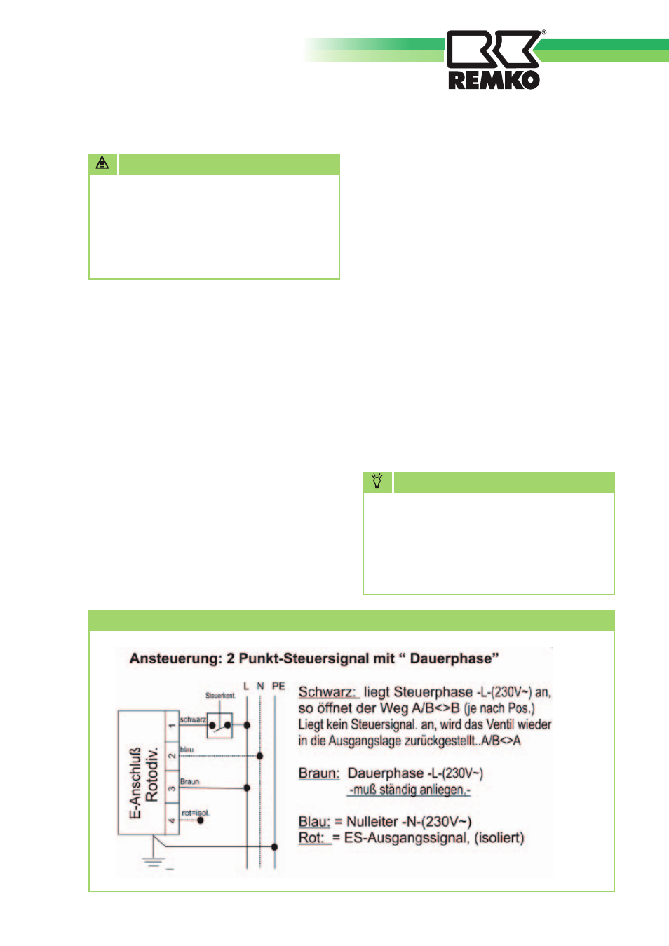
Actuator connection diagram
■
Limit switches are integrated in the
actuator of the 3-way switching
valve.
■
The actuator requires a continuous
operating voltage of 230V/1~/50Hz.
This must be connected to the brown
(L) and blue (N) wires. In this state
the valve is in resting position. This
corresponds to heating position and/
or opening of the path AB<->B.
■
The valve is actuated if the black
wire of the actuator is addition-
ally connected to a voltage of
230V/1~/50Hz. The valve then
turns 90
°C until it reaches the limit
switch. This, in turn, corresponds
to the hot water or cooling position
and/or opening of the path AB<->A.
The valve remains in this state until
the voltage is disconnected from the
black wire again.
■
Every heat pump has appropriately
labelled connection terminals for the
connection of the actuator.
Observe the instructions in the
installation manual of the heat
pump for the correct connection.
(Connection diagram and circuit
diagrams, if applicable)
NOTE