Customer service and guarantee, Environment and recycling, Internal wiring diagram – REMKO RKV 10 W User Manual
Page 18
18
Operation/handling which does not comply with
these instructions is prohibited!
In cases of non-compliance, we assume no liability
and the guarantee becomes null and void.
Customer Service and
Guarantee
For the guarantee to be valid, the purchaser or his cus-
tomer must completely fill out the "guarantee certificate"
enclosed with all units and send it back to REMKO GmbH
& Co. KG
.
The units are repeatedly tested at the production site to
ensure that they are working properly. If a malfunction
occurs that cannot be eliminated by the operating per-
sonnel, please contact your dealer or contact person.
Proper use
The indoor units have been designed and fitted exclu-
sively for operation with REMKO outdoor parts belong-
ing to the RKV and RKM series.
The manufacturer assumes no liability for damage re-
sulting from non-compliance with manufacturer specifi-
cations and legal requirements, or if modifications are
made to the units.
We reserve the right to make changes to dimensions and design in the interest of technical progress..
Only authorised personnel may come into contact with
the cold cycle. This ensures that refrigerant does not es-
cape into the environment when the unit is being re-
paired. Both the refrigerant and the system parts are
subject to special requirements for disposal.
The refrigerant in use is a safety refrigerant. This means
that, should damage occur, the quantities released will
not cause injury to the respiratory systems of people
and animals.
Important information about recycling!
Environment and
Recycling
Do not touch the liquid refrigerant as it can freeze the
skin!
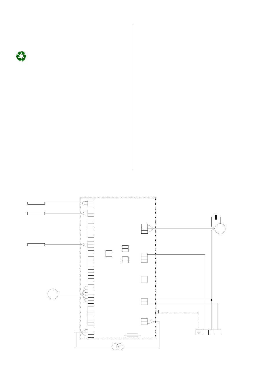
Internal Wiring Diagram
RKV 10 W, RKV 13 W, RKV 18 W, RKV 24 W
P4
ODF
P3
FIN
P2
Sensor Einfrierschutz
TEMP
P1
Sensor Umluft
Door
P5
Reed Kontakt
Ansauggitter
P6
JP3
P7
P8
P9
STEP 2
STEP 1
12-0-12
JP1
JP2
J1
J2
2 N A
J3
J4
J5
ws
rt
FM
FL
FH
ge
bl
Swingmotor
M
Transformator
Sicherung
M
Kondensator
Ventilator-
motor
sw
RV
CP
or
OF
Klemmleiste
(falls vorhanden)
CP = Kompressor
A = Outer conductor
N = Neutral conductor
2 = Control conductor (compressor contactor)
Fuse 3 A
Terminal strip
Condenser
Compressor
Oscillating motor
CP = Compressor
Fan motor
Reed contact
Air intake grille
(if available)
Frost protection sensor
Circulation sensor
ge = yellow
bl = blue
sw = black
or = orange
ws = white
rt = red