Condensation connection, External condensation pump – REMKO RKV 10 W User Manual
Page 15
15
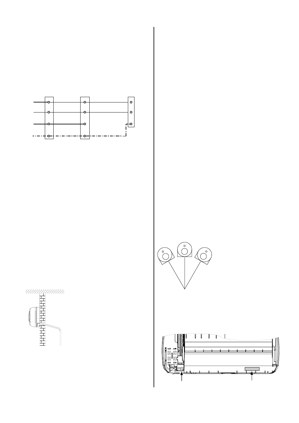
Electrical connection of the units:
Red
White
Orange
Yellow-
Green
Terminal strip
outdoor part
To the compressor
contactor
Protective conductor
Terminal strip
power supply
Terminal strip
indoor unit
A
N
2
L1
N
A
N
2
PE
PE
PE
Control
conductor
Neutral conductor
Outer conductor
230 V~,
50 Hz,
L1
N
PE
2 % incline
à
Always use suitable hose clips.
à
If the condensation is being guided to a drainage
line, please install a siphon-like hose guideway which
acts as an odour seal.
à
After the hose has been laid, check to make sure
that condensation can drain freely.
à
Make sure there is an adequate
incline for drainage.
It must be at least 2 %!
à
If the supplied condensation
hose is not long enough, it can
be attached to standard hoses
with a 17 mm inner diameter.
Condensation Connection
Condensation forms on the plate fin exchanger of the
indoor unit during cooling operation because tempera-
tures below the dew point are reached.
The indoor unit is equipped with a collection tray and a
condensation hose for the condensation that accumu-
lates.
Follow the instructions below to lay the condensation
hose:
à
The condensation drainage line is generally placed in
the same guideway as the refrigerant lines.
à
If, as a result of structural design conditions, it is
necessary to have a different guideway for the con-
densation hose, the hose can also be guided to the
indoor unit through a different drain.
à
If the unit is being operated at outside temperatures
below 0°C, the lines must be placed in such a way
that they are protected from frost.
External Condensation Pump
The condensation pump which can be purchased as an
accessory (Ref. no. 1613167) transfers the condensa-
tion which accumulates in the indoor unit to drains that
are placed in inconvenient locations, even if the drain is
located above the unit. The pump can be installed in-
side the unit.
Follow the operating instructions for the pump as well as
the instructions below:
à
Protect the housing from coming into direct contact
with the condensation.
à
Never open the housing of the pump.
à
Check the operating current of the pump and the
power supply for consistency.
à
Use the alarm contact to switch off the outdoor part.
à
Keep in mind that you should only use the alarm
contact together with a contactor or relay to switch
off the outdoor part, depending on the load.
à
Connect the pump securely to the control line.
Pump
The pump is attached to the right side of the unit (seen
from the back) using the supplied, self-adhesive strips.
Reservoir
Pump
Reservoir with sensor
The reservoir collects the condensation. A sensor
switches the pump on when a specific water level has
been reached.
The electronic sensor allows the reservoir to be rotated
by up to 30° on its axis.
Possible assembly positions:
Rotation of the axis up to 30°
to the right and left.
The condensation pump consists of 2 components:
à
The reservoir with sensor
à
The pump
6. Connect the unit to the current-free line from the out-
door part.
See figures.
7. Reassemble the unit.