REMKO RKV 10 W User Manual
Page 13
13
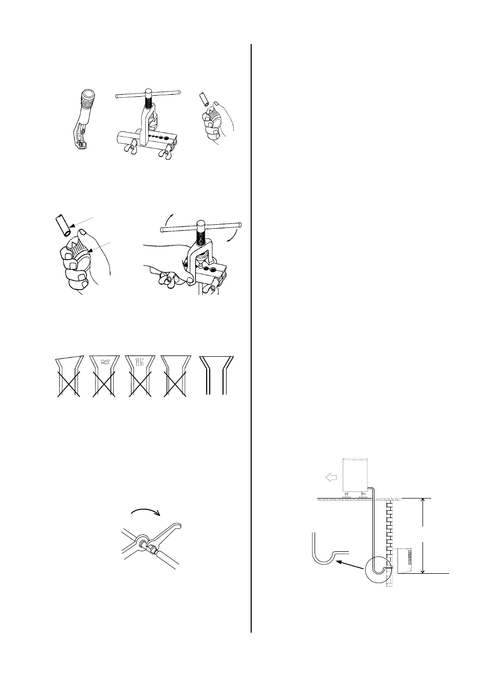
uneven
thickness
formation
of cracks
formation
of cracks
rippled
CORRECT
9. Make sure that the flare has the correct shape.
Only tools approved for use in cold conditions may
be used.
Deburrer
Refrigerant line
Flare tool
If the length of the connection line is longer than 5
m, refrigerant must be added to the system during
initial operation.
See the section Adding Refrigerant.
Counterpressure
open-end wrench 1
Counterpressure
open-end wrench 2
10. First manually connect the refrigerant lines with the
shut-off valves and the bolts to ensure that they are
in the proper position.
11. Now tighten the bolts using 2 open-end wrenches
that have a large enough opening.
12. Use a second wrench to apply counterpressure
when tightening.
Oil recirculation
If the outdoor part is set up at a higher level than the in-
door unit, appropriate steps must be taken for oil recir-
culation.
Radius:
50 mm
Outdoor part
maximum
10 m
Indoor unit
Oil elevation arc in the
suction line to the outdoor
part 1x for every 2.5 m
This is usually accomplished by creating an oil elevation
arc that is installed every 2.5 meters of line going up.
6. Use only the tools below for assembly.
15. If you have selected Option 2 or 4 (drainage through
the wall), guide the condensation water and control
line through the wall lead-through to the indoor unit.
If you also need a condensation pump, it must be in-
stalled beforehand.
16. If, due to structural design conditions, it is not possi-
ble to guide the condensation line through as well,
make sure that the condensation can drain freely at
all times.
17. Hang the indoor unit leaning slightly to the back in
the previously assembled wall mount and press the
bottom of the unit into the mount.
18. Lay the refrigerant lines from the indoor unit to the
outdoor part.
19. Make sure that the refrigerant lines are adequately
secured.
20. Take steps, if necessary, to ensure oil recirculation
as described in the section on oil recirculation.
21. Place the control line in the same line guideway.
22. Remove the protective caps supplied and the swivel
nut caps of the shut-off valves and use these for
continued assembly.
23. Connect the refrigerant lines to the outdoor part as
described above.
7. Before you flare the refrigerant lines, ensure that
there is a swivel nut on the hose.
8. Work with the refrigerant lines as shown in the figure
below.
13. Insulate the installed refrigerant lines including the
connector against heat.
14. Only use insulation hoses sealed against diffusion
that are suitable for this temperature range.