REMKO RKV 10 W User Manual
Page 16
16
Initial operation of the condensation pump
Before putting the pump into operation, the lines that
have been laid must be checked to ensure that they are
functioning properly and leakproof.
1. Switch the power supply of the pump on.
2. Pour distilled water into the condensation tray until
the pump switches on from the reservoir.
3. Pump operation can be heard when it is being oper-
ated for the first time or being put back into opera-
tion.
After it has run for short period, the noise normalises.
4. Keep in mind that the pump automatically switches
off once the water has been pumped out of the res-
ervoir.
5. If, upon initial operation, there is a lot of noise from
vibrating hoses, insulate these hoses using foam
hoses.
Condensation buildup is prevented when using insu-
lated hoses sealed against diffusion.
6. Check the function of the alarm contact by drastically
increasing the amount of water.
The alarm contact should switch off the unit.
Prior to performing any work on the unit, it must be
unplugged from the power supply and secured
against being inadvertently switched on!
Connections of the condensation pump on the wa-
ter side
The reservoir is attached to the condensation collection
tray connection of the indoor unit via a customer-
supplied hose (20 mm Ø). The factory-installed flexible
hose of the condensation tray must be disassembled.
The reservoir and pump are connected to one another
with the long suction hose and the pluggable sensor line
from the reservoir. To ensure that the pump operates as
quietly as possible, the suction hose should not be
shortened.
The supplied ventilation hose must be used for the res-
ervoir to function properly. The end of the ventilation
hose must at least be at the same height as the con-
densation tray to prevent water from overflowing.
The supplied metal wire clips are used to secure the
hose in a vertical position. Keep the hose from being
suspended which will prevent an air pocket from form-
ing.
The 6 mm (inner diameter) thick hose is placed at a
maximum height difference of 6 meters to the drain.
The condensation line should be as vertical as possible
to guide the condensation.
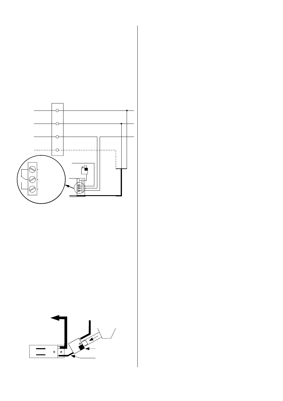
Electrical connection of the condensation pump
The electrical connections may only be made by author-
ised service personnel in accordance with the relevant
regulations.
There is an electrical connection area located under the
hose connections. This area also a cover that can be
taken on and off.
The pump is equipped with an alarm contact that
switches off the indoor unit and can also control a cus-
tomer-installed malfunction/alarm system.
If the pump is installed outside the unit, a maxi-
mum height difference of 3 m between the lower
edge of the unit and the pump mounted above
may not be exceeded.
Störung /
Alarm
Steuerleiter
Innengerät
Steuerleiter
Außenteil
Außenleiter
Neutralleiter
Steuerleiter
Innengerät
Schutzleiter
Steuerleiter
Außenteil
A
N
PE
Störung
Innengerät
Pumpe
fest verdrahtete
2
Rot
Weiß
Orange
Gelb-Grün
Ge
lb
-G
rü
n
Bl
au
Br
aun
Netzzuleitung
Indoor unit
Red
White
Orange
Yellow
-
green
Outer conductor
Neutral conductor
Control conductor
indoor unit
Control conduct.
outdoor part
Y
ello
w
-
green
B
lue
Br
ow
n
Protective conductor
Malfunction
/Alarm
Control conduct.
indoor unit
Control conduct.
outdoor part
Malfunction
Pump
Permanently wired
power supply line
Kondensatab-
laufschlauch
Entlüftungsschlauch
(kurz)
Pumpe
Reservoir
Ansaugschlauch
(lang)
Tropfwanne
Condensation
drainage hose
Ventilation house
(short)
Pump
Collection tray
Reservoir
Suction hose
(long)