Remko rks, Assembly instructions for specialist personnel – REMKO RKS 435 H User Manual
Page 8
Assembly instructions for specialist personnel
Important information before
installation
■�
�or in��tallation of the entire
��y��tem, the in��tru�tion�� in the
operating manual�� for the in-
door and outdoor unit�� mu��t be
followed.�
■�
Bring the unit a�� �lo��e a�� po��-
��ible to it�� in��tallation lo�ation
in it�� original pa�kaging.� Thi��
prevent�� any tran��port damage.�
■�
Che�k that the �ontent of the
pa�kaging i�� �omplete and
in��pe�t the unit for vi��ible tran��-
port damage.�
Report any defe�t�� immediately
to your �ontra�tual partner and
the �arrier.�
■�
Lift the unit at the �orner�� and
not at the refrigerant or �on-
den��ation �onne�tion��.�
■�
The refrigerant pipe�� (inje�-
tion and ��u�tion pipe), valve��
and the �onne�tion�� mu��t be
in��ulated to ��eal them again��t
vapour diffu��ion.� �f ne�e����ary,
the �onden��ation pipe ��hould
al��o be in��ulated.�
■�
Choo��e an in��tallation lo�ation
that en��ure�� a free air inlet and
outlet.� (See “Minimum �lear-
an�e��” ��e�tion.�)
■�
Do not in��tall the unit in the im-
mediate vi�inity of equipment
that radiate�� a large amount of
heat.�
�n��tallation �lo��e to heat radia-
tion redu�e�� the performan�e of
the unit.�
■�
Do not open the blo�king
valve�� for the refrigerant pipe��
until the entire in��tallation pro�-
e���� i�� �omplete.�
■�
Seal open refrigerant pipe��
again��t the ingre���� of moi��ture
u��ing appropriate �ap�� or ad-
he��ive tape�� and never kink or
�rimp the refrigerant pipe��.�
■�
Avoid unne�e����ary bend��.� Thi��
minimi��e�� the pre����ure lo����
in the refrigerant pipe�� and
en��ure�� a free return flow of
�ompre����or oil.�
■�
�n parti�ular, you ��hould take
pre�aution�� to en��ure the oil
return if the outdoor unit i�� po-
��itioned above the indoor unit.�
(See “Oil return mea��ure��”
��e�tion.�)
■�
�f the ba��i� length of the refrig-
erant pipe ex�eed�� 5 metre��,
refrigerant ��hould be added.�
�or the quantity of additional
refrigerant, refer to the “Add-
ing refrigerant” ��e�tion.�
■�
���e ex�lu��ively the refriger-
ant pipe ���rew �ap�� ��upplied
and do not remove them until
��hortly before �onne�tion to the
refrigerant pipe��.�
■�
Set up all ele�tri�al �onne�tion��
in line with the appli�able D�N
and VDE regulation��.�
■�
Alway�� ��e�ure ele�tri�al line��
properly in the ele�tri�al termi-
nal��.�
Otherwi��e, fire �ould be
�au��ed.�
Wall feed throughs
■�
A wall feed through of at lea��t
70 mm in diameter and with
a 10 mm gradient from in��ide
to out��ide mu��t be �reated for
ea�h indoor unit.�
■�
We re�ommend that the hole i��
padded out in��ide or lined, e.�g.�
with a PVC tube, to prevent
damage to the pipe��.�
■�
When in��tallation i�� �omplete,
the wall feed through mu��t be
��ealed with an appropriate ��eal-
ing �ompound.�
Do not u��e material�� �ontaining
�ement or lime.�
Installation materials
The outdoor unit i�� either ��e�ured
to the wall u��ing 4 ���rew�� and a
wall bra�ket or atta�hed to the
floor u��ing a ba��e bra�ket.�
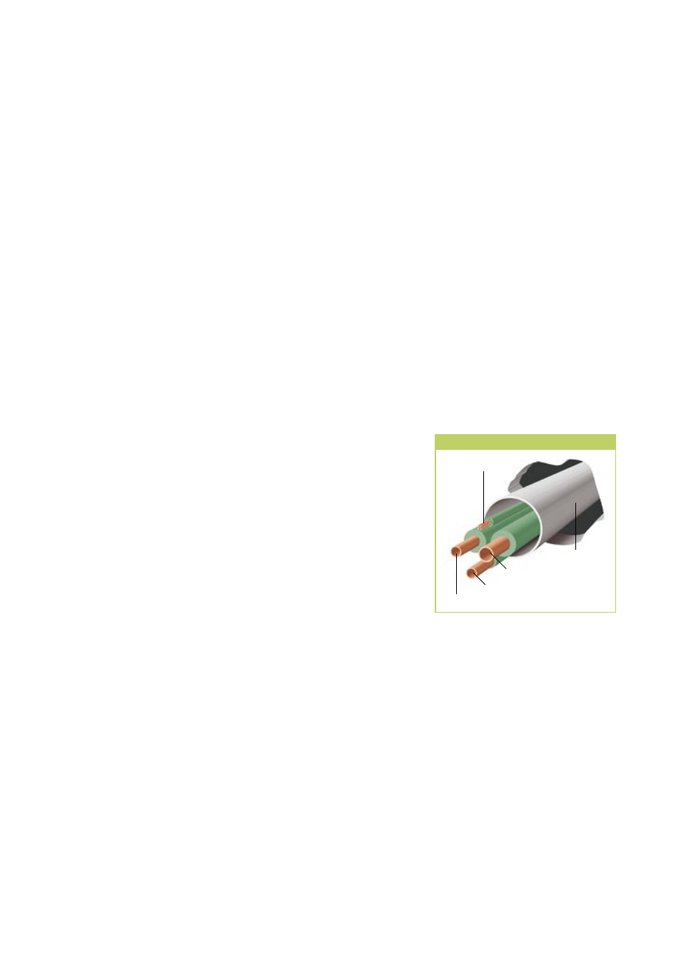
Pipes in wall lead through
Control line
Conden��ation pipe
�nje�tion pipe
Su�tion pipe
PVC pipe
REMKO RKS
8